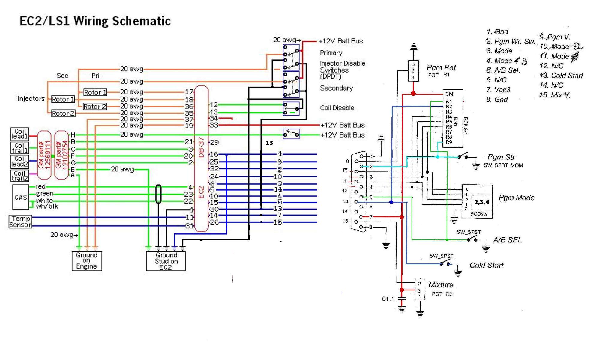
I notice that Tracy uses a separate ground for the injectors.
He is not fooling. If you connect the battery ground to the
injector ground it wont work. He should have mentioned
that. It is an attempt to keep the injector spikes out
of the computer. IMHO a few chokes here and there would also
have worked without the uncertainties :)
Paul Lamar
Not necessarily -- putting the currents where you want them, where they
don't share common impedance paths, is a better approach. "Chokes here
and there" doesn't work very well unless you have a lot of energy
storage in the power supply so it never sees the spikes anyway.
Otherwise you will always be fighting the voltage spikes on the computer
power that follow the current spikes from the injectors. Strongly
recommend Henry Ott's book "Electromagnetic Compatibility Engineering."
It's mostly about meeting EMC requirements but the issues are the same.
His earlier version "Noise Reduction Techniques in Electronic Systems"
is just as good for this problem.
David Josephson
True! Capacitors are needed. A 1000 Uf and a small choke on each injector
would work well I suspect. Worth a try. Of course the computer is well
grounded to the engine.
Even better is mount the switching transistor on the injector like a
smart coil.
Thanks for the book tip. I'll get it.
Paul Lamar
--
Maybe this discussion should be offline, but having wrestled this
particular demon for decades in the audio and instrumentation biz I can
assure you that "I suspect" approaches (even mine, or especially mine)
are often a waste of time. It is tedious engineering but it is doable
without too much exertion. Your number one question, for every instant
of time for a given injector pulse, is "where does the current flow?"
From battery + back to battery -, figure out the resistance of each
path and see how the current through an injector gets there and back.
I am not sure that putting the switching transistor at the injector
would help. I would rather have the switching transistor where the
source impedance for power feeding it was lowest. Yes, the loop area for
radiated EMI would be reduced, but then you have another handful of
connections that are more subject to engine vibration. What is a "small
choke" and what function does it serve? Why 1000 uF and where would you
put it?
David Josephson
What ever happens please put your response at the bottom of the thread
and sign it so it makes it easier to read and follow.
Smart coils have no problems with ground loops nor does tracy use a
separate ground for the smart coils. The switching transistor is in the
coil.
Paul Lamar
The Rotary Engine News Letter. Powered by Linux.
ACRE NL web site.
http://www.rotaryeng.net
You Tube
http://tinyurl.com/beqqxas
Copyright 1998-2014 All world wide rights reserved.

