ARDUINO boards/chips are programmed with a bootloader. The
developers of the ARDUINO finally implemented the STK500V2
communications protocol. This protocol is supported by Atmel and of
course by BASCOM.
Select the ARDUINO STK500V2 programmer in BASCOM programmer options
to use this communications protocol.
A board like the MEGA2560 R3 uses this communications protocol and
probably all newer AVR based ARDUINO boards will support this
protocol.
BASCOM AVR is superior to Arduino IDE. Bascom is simpler and much
more flexible. In fact, Bascom is the language used by the majority
of hobbyists.
C is more for professionals.
https://www.youtube.com/watch?v=Ppdpp4pqeQc$regfile = "attiny26.dat"
Simple blink program. Think of the LED's as injectors.
$crystal = 1000000 $hwstack = 32 $swstack = 8 $framesize = 24
Config PORTA = Output Config PORTB = Output
RED Alias PORTB.0 YEL Alias PORTB.1 GRN Alias PORTB.2
Begin:
Red = 1 : Yel = 0 : Grn = 0 Wait 1
Red = 0 : Yel = 1 : Grn = 0 Wait 1
Red = 0 : Yel = 0 : Grn = 1 Wait 1
Goto Begin
The first section sets up the chip, then we need to configure the two
ports. A port can be an INPUT or an OUTPUT. Since we want to run some
LEDs, we set the port to be an OUTPUT. May as well define them all at
one time... so we did.
The next section is where we define the pin names. I don't know about
you... but I would forget which pin the RED LED was connected to, or
the green, or the yellow. I don't feel like typing in *PORTB.0* for
the first pin every time... so we told the software that it's name
was "RED". Now all we need to do is reference it by it's name.
Once defined, if we make them equal a "1" the LED will turn ON, and
if we make it equal to a "0" it would turn OFF. The next series of
lines defines how we want the LEDs to be set, then waits 1 second.
(The
*WAIT* command.)
After we change the state of the LEDs 3 times... we jump back to the
beginning and do it all over again... over and over.
This is simple enough for every one and a simple open source EFI is
very doable.
Paul Lamar
------------------------------------------------------------------------
A programing language can be over whelming at first glance.
The way to proceed is cherry pick only the instructions you need to
do the job. Here is a book on the Bascom language.
You need to know:
1. How to set a bit in a port that turns on an injector 2. How to
read an analog value in from a MASS airflow sensor 3. How to use WAIT
as a delay to keep the injector on for a specific time. See the
program source code above. 4. How to handle hardware interrupts.
This basically is all you need and a little math for a simple EFI
that will run the engine. You also need a stand alone ignition of
course.
If you put a potentiometer in parallel with the mass air flow sensor
that will provide a leaning function. Just like the leaning control
on aircraft engines. When the pot knob is set to full rich the
injector width is set for about 10 pounds of air to one pound of
fuel. When full lean it should be about 18 to 1.
To keep it simple the program checks the mass airflow every half
second and adjust the mixture over and over again.
The simple way to do this is use an external 50 cent CMOS 555 osc
oscillating at two cycles per second (2 Hertz in the silly French
system :)) and connect it to a hardware interrupt pin. It is not
timed fuel injection. It is called batch mode and works fine for an
aircraft engine. Tracy's EFI system was batch mode.
Paul Lamar
Paul,
No need for the extra timer. Just check MAF in your loop. I don't
think it matters if the flow is adjusted every 5ms or 500ms.
Henry
The trouble is how does the program know 500 ms has elapsed? There is
no ON TIME hardware interrupt in Bascom like there is in QB as far as
I know at this point in time. (Pardon the pun)
Obviously the more you pulse the injector the more fuel you get.
Send me the BASIC source code of what you have in mind.
Paul Lamar
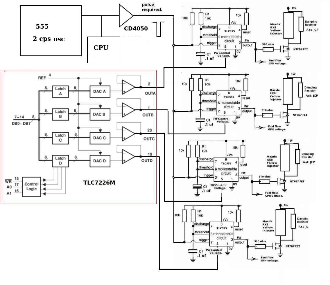
I am thinking along the lines of your 555 injector, together with a
BASIC computer.
* The BASIC computer continues to monitor the MAF sensor, and from
there, it knows the flow rate of air per second.
* It also knows the rpm,
* It can calculate amount of fuel needed in x number of m.sec. of
injector on time per revolution.
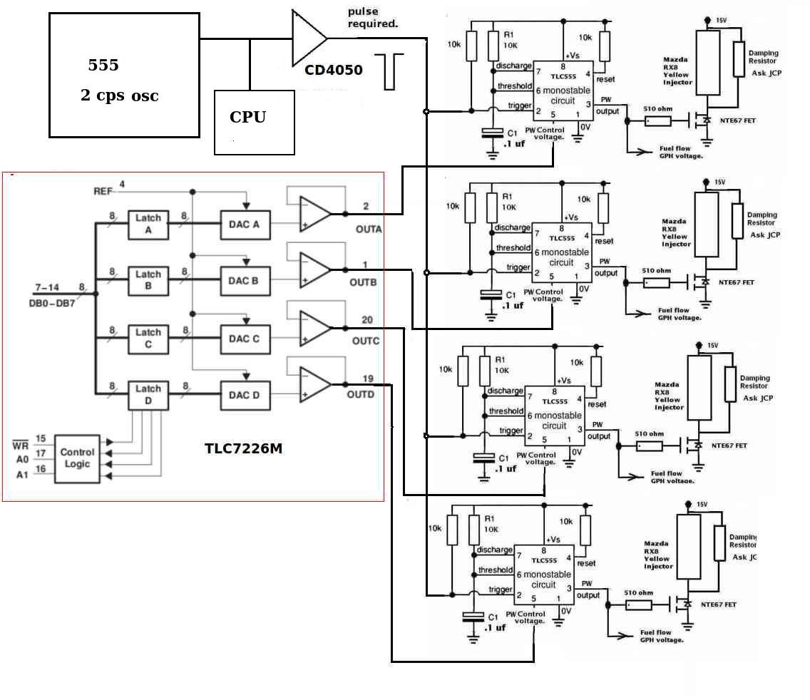
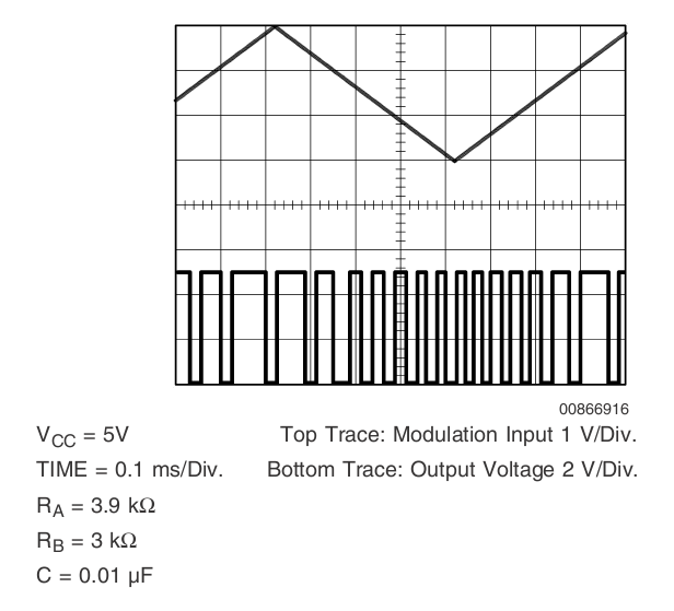
* Assuming that you have a voltage to pulse width table for the 555
timer, the computer can send an analogue signal to control the 555
timer.
* Each ignition trigger will also trigger the 555 timer, giving the
exact amount of fuel.
Mission accomplished.
Regarding inputs, we can use an analogue signal to inform the BASIC
computer what the rpm is by using A to D converter, and then do a
table lookup to find the current rpm. Much easier to do than digital
measurements. We can calibrate the sensor before installation to get
accurate rpm from the analogue signal.
With CHT, we can even implement auto leaning! Or, simply use another
VR to supply the BASIC computer with in indicator on how much fuel to
lean.
Henry
That certainly reduces the processor software over head sitting in a
wait loop for the
injector on time. That frees up the processor time for all sorts of new
jobs.
Here are some old schematics on the scheme.
Paul Lamar
The Rotary Engine News Letter. Powered by Linux. ACRE NL web site.
http://www.rotaryeng.net You Tube
http://tinyurl.com/beqqxas
Copyright 1998-2014 All world wide rights reserved.