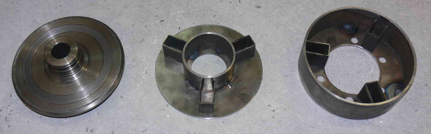
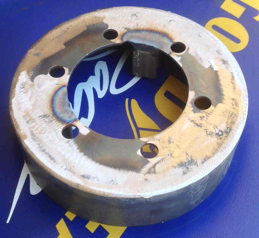
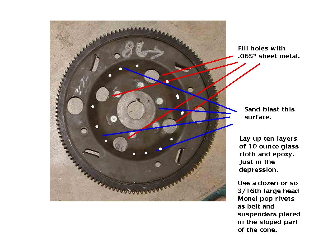
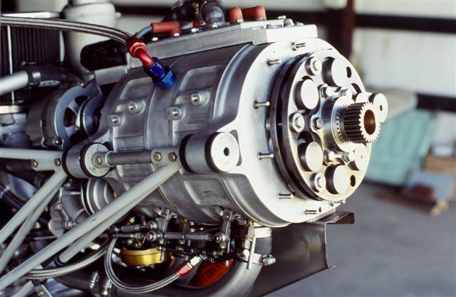
Paul,
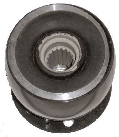
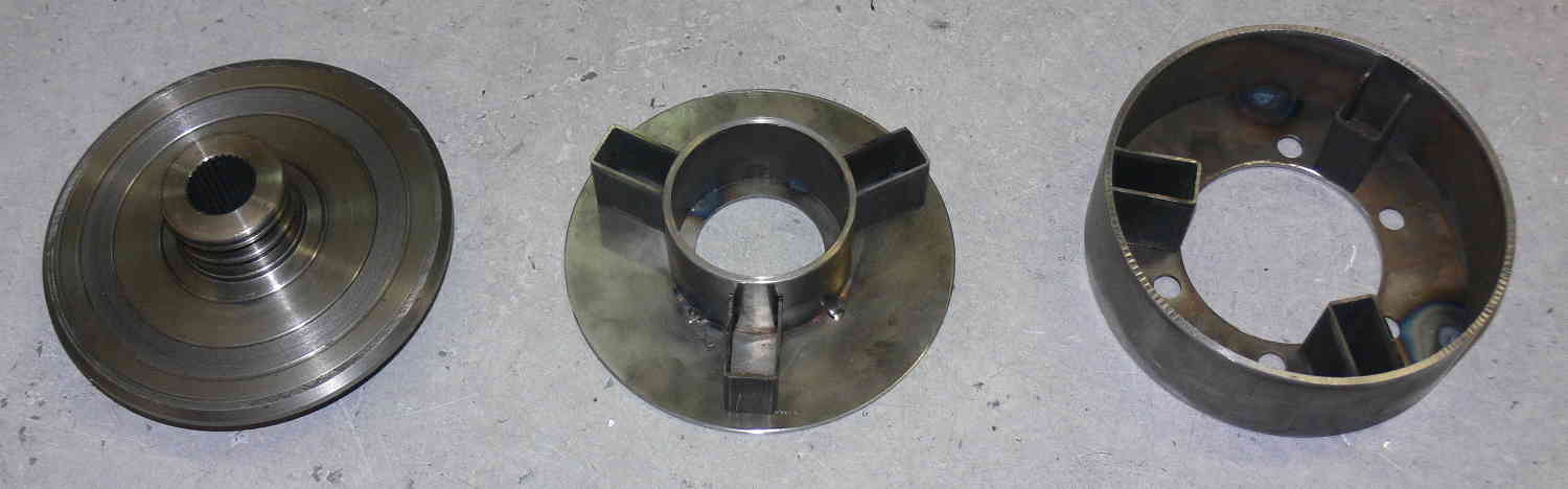
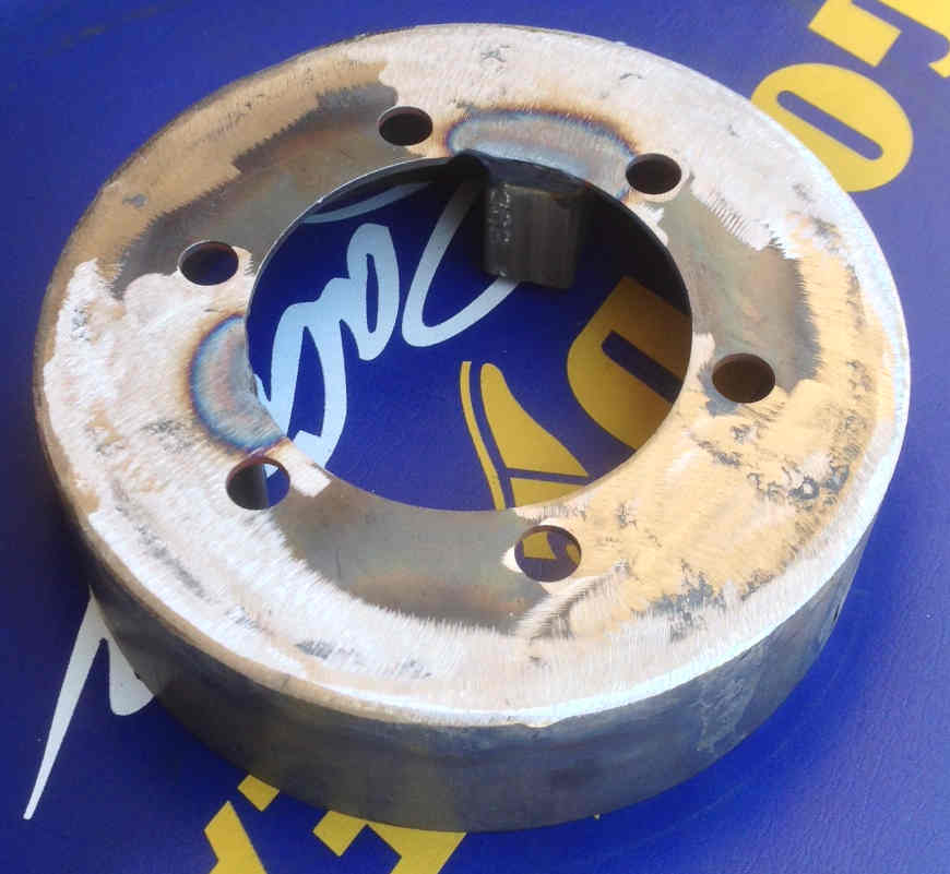
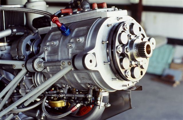
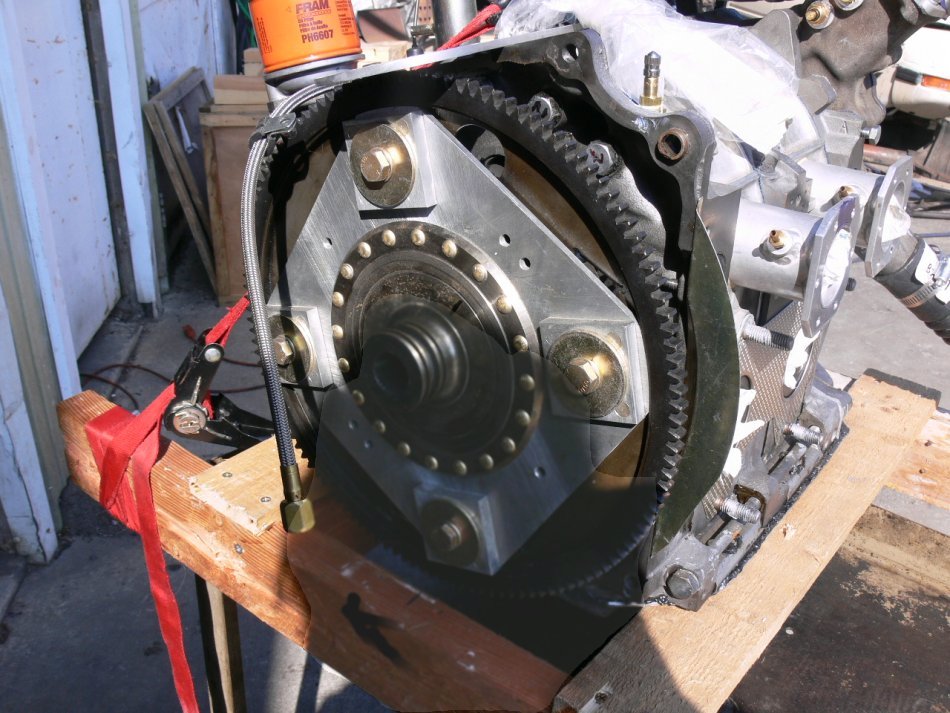
Thanks for the gear box/speed reducer pics - Interesting - A few
questions -
1 - Good lifetime on the needle bearings ??
2 - Looked like uncaged bearings ??
3 - Presume the 10 lb heavier unit used some other type of bearings
??
4 - What provisions for lubrication ??
5 - The drawings have all the appearance of a multi-thousand dollar
product - Price range ??
6 - Cooling problems - I would think that there might be some with
uncaged needles ??
7 - Doesn't look like a particularly difficult project from a
machining perspective -
8 - Presuming outer housings are aluminum castings - Patterns exist
??
Roland Friestad
You must keep the RPM on the needle bearings down. Particularly on
the thrust needle bearings. Those tiny needles are really zinging
around in there. We have a lot of experience on this. Some people
have worn them out. That is the reason for three back to back. The
RPM on any one is one third of the total.
The shaft, surprisingly, does not get any load on the bearings until
the aircraft stalls or spins. Characteristic of planetary gear sets
as all side load is canceled out. Hard to imagine but true. Those
give no problem and they are much lighter, as is the housing, if they
were ball or tapered rollers. Win win situation not to mention much
lower cost all around.
Note the extended point set screws are better and easier to machine
than splines. All back lash is eliminated.
I have an account set up with a local wholesaler of tranny parts. I
make no money on them I just charge cost plus shipping. The 3.17 gear
set is just under $200.
The box can be built for under 5 or 6 hundred in parts. It all
depends on what the NC shop charges.
Shares synthetic oil with the engine. BTW the oil stays clean in a
rotary. Uses the engine oil cooler.
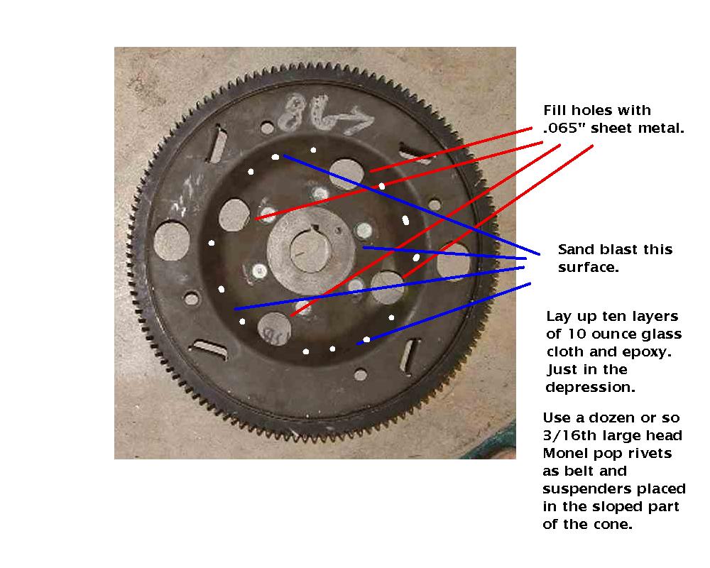
Here is some more stuff on the subject from 16 years exp. :)
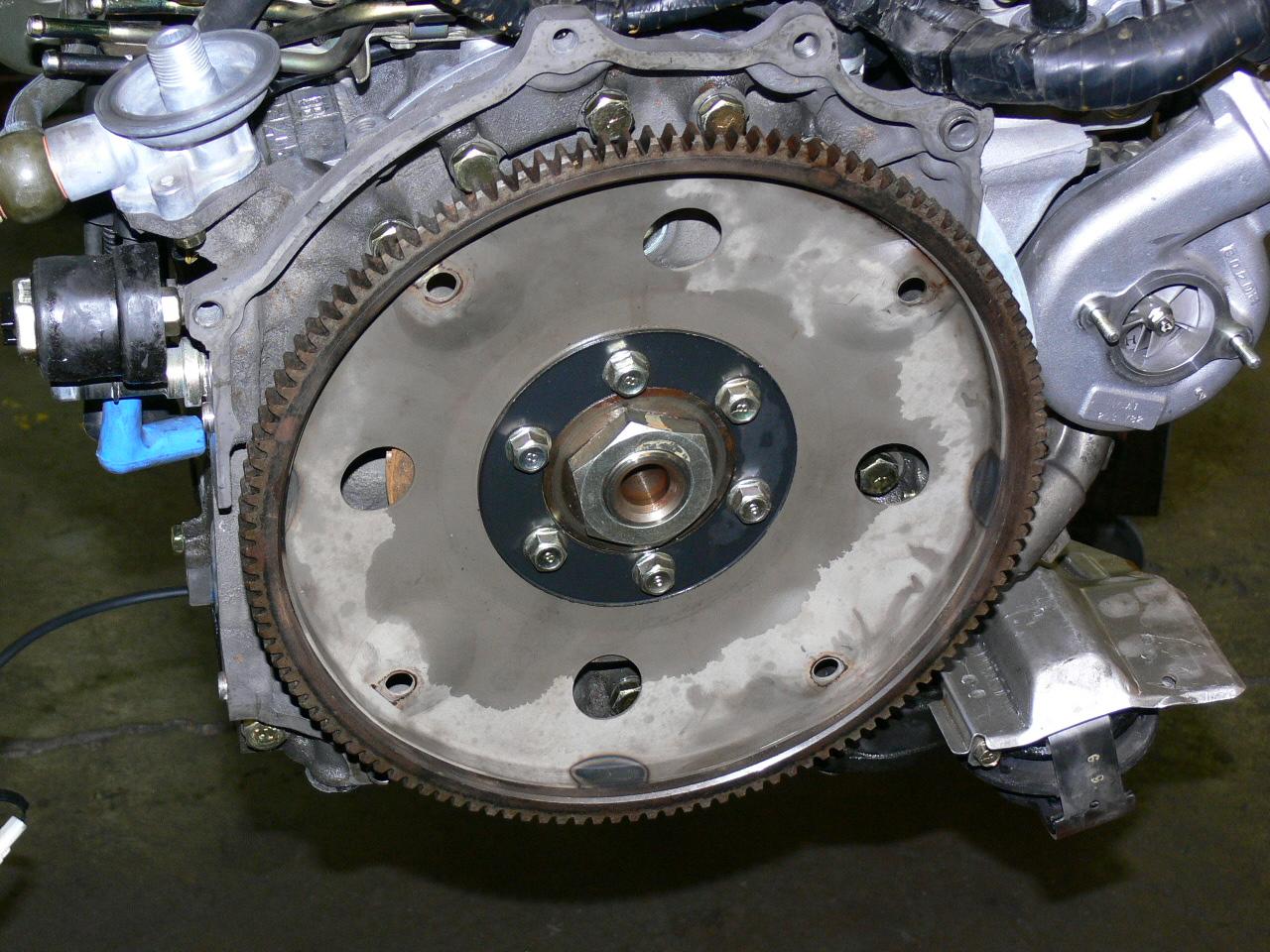
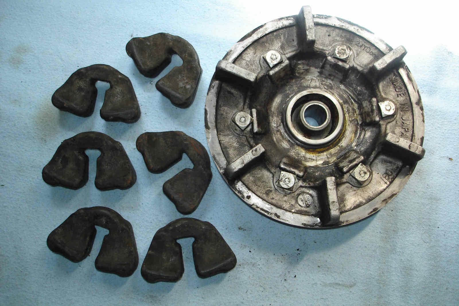
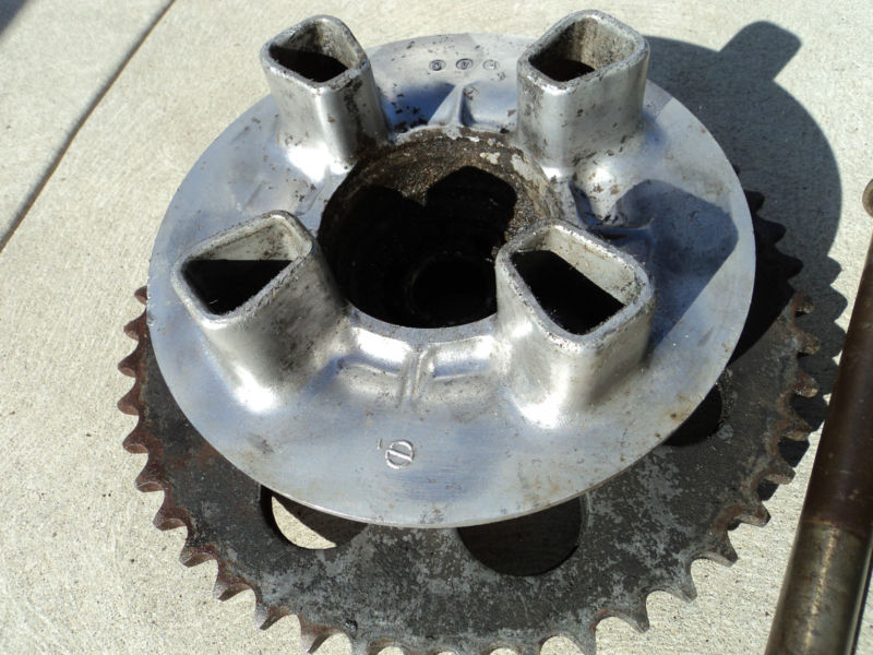
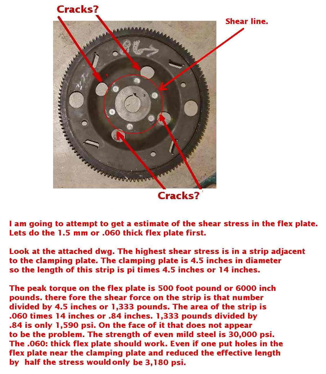
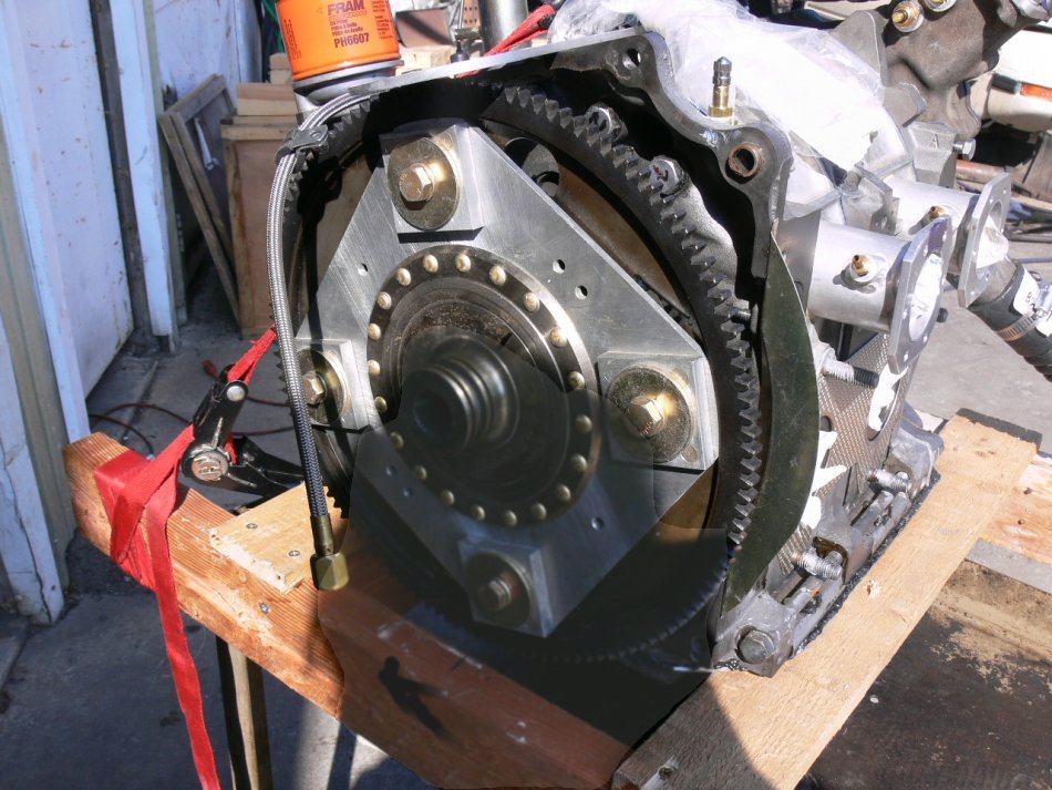
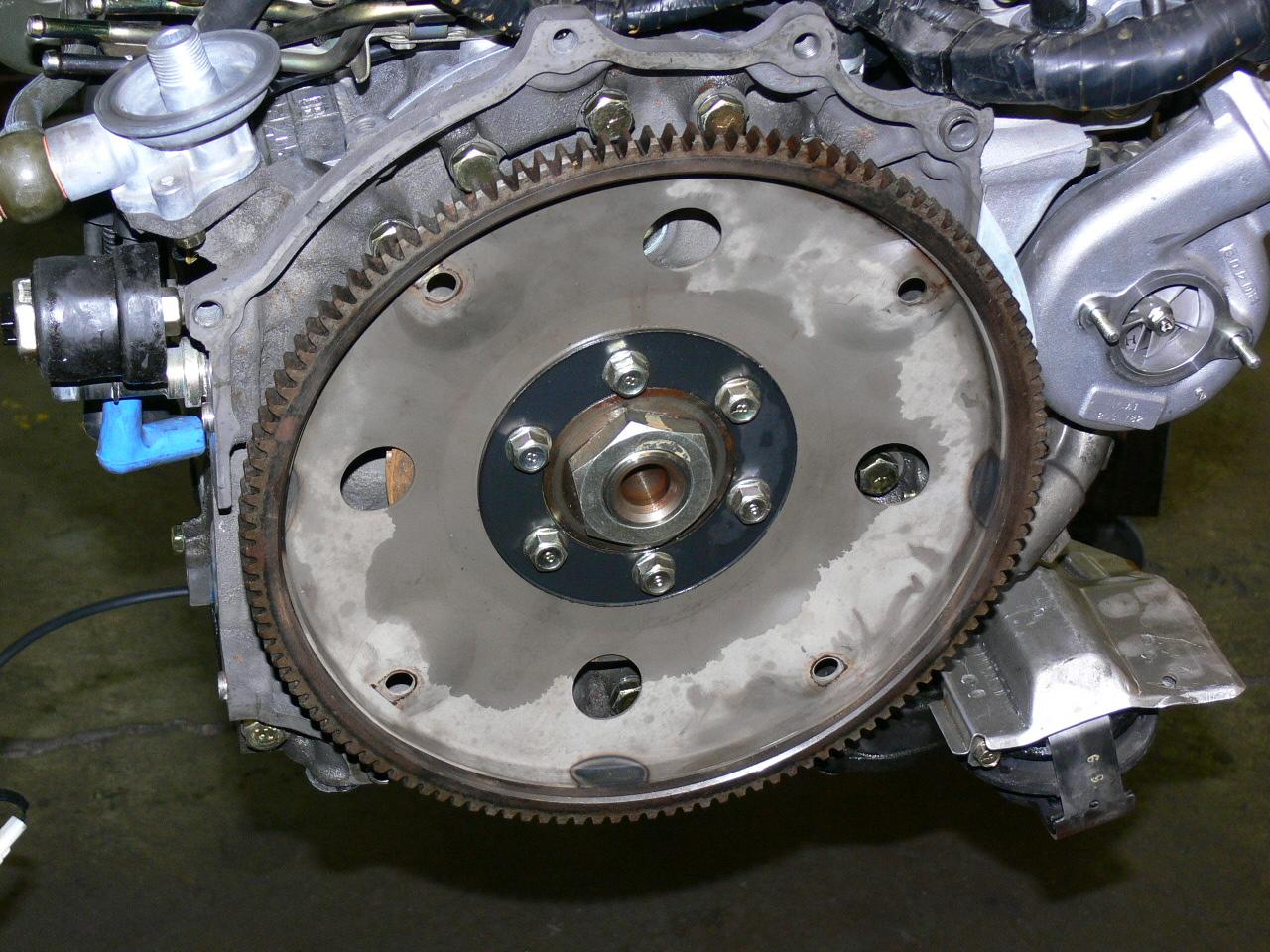
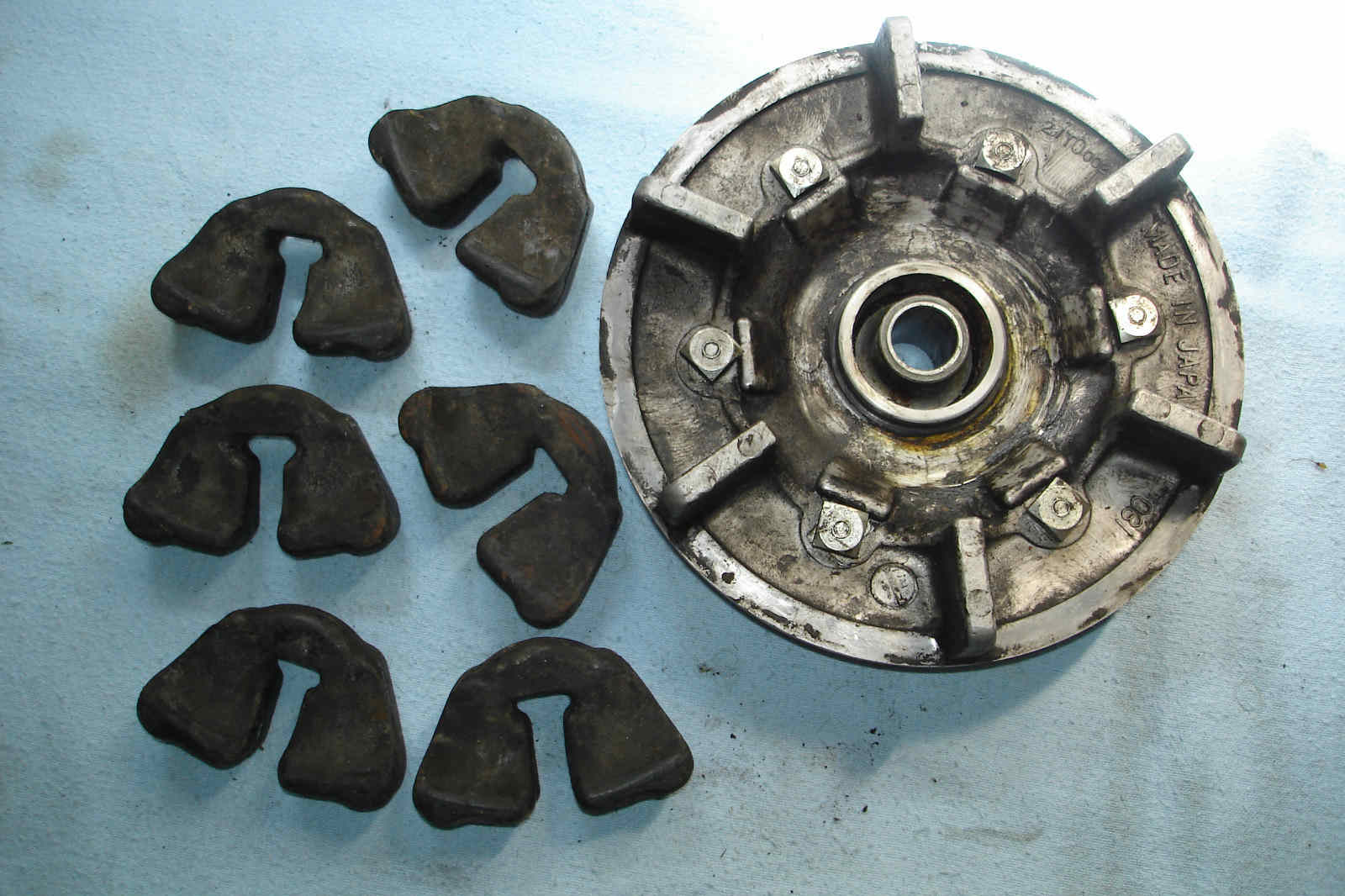
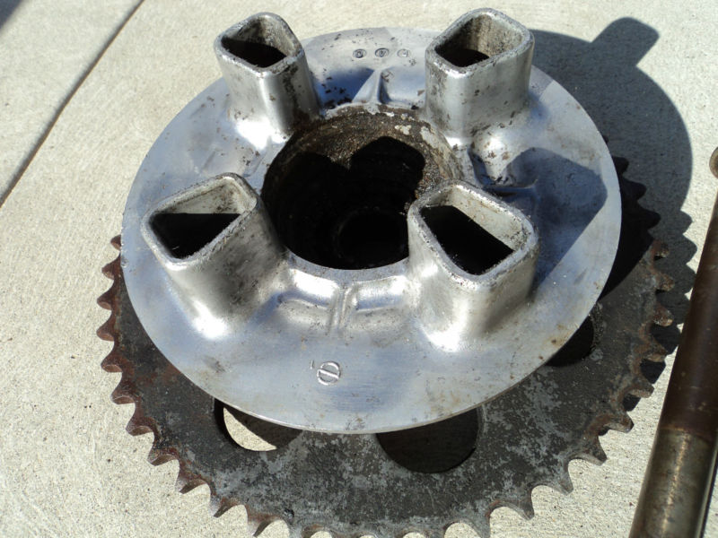
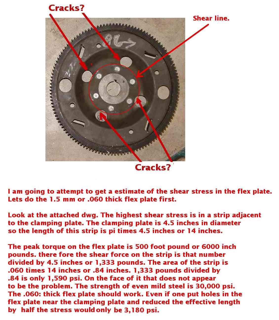
There will be more on the rubber coupling with the engine.
Paul Lamar
Paul and Roland,
Glad to see motion on this project. Plenty of people would be happy to
pay $2-4K for a competently done redrive in the 100-200 hp range. The
extra cost is for support -- good engineering and documentation so that
people can figure out where their problems are and how to fix them. The
only thing worse than being on a schedule to deliver things is being on
the hook for phone support when stuff breaks. The planetary system and
bearings are entirely known technology; where there isn't a proven
system, and a lot of trouble remains, is in handling of torsional
vibration.
Rotary engine power pulses will be at a higher frequency, which makes
some problems easier and takes some solutions off the table. It would be
worthwhile to make aany new design applicable to a range of powerplants,
not just rotary.
At some engine speed, the frequency of its power pulses will resonate
with the spring constant of its drive shaft, gearbox, propeller shaft
and the inertia of the rotating prop. At this frequency, each engine
pulse meets the reflection of the previous pulse delayed through the
compliance of the system, and causes a huge increase in torsion
throughout (at other frequencies the reflected pulse doesn't exactly
meet the outgoing pulse and therefore doesn't reinforce.) The engine is
pushing one way while the inertia is pushing back the other way,
doubling the torque in the shaft at the first pulse. The peak torsion
can exceed 20 times each individual torque peak because each successive
pulse adds more energy to the spring formed by the shaft. The key to a
successful redrive design will be to know exactly what's going on and
build something that will never get to a destructively resonant
condition. There are many methods of achieving that, but you won't know
you're there until you have modeled the system mathematically and proved
that your model is accurate by testing.
We need to: (1) design the compliance of the system so that the
resonance, with all values of propeller inertia, lies outside the ground
and flight operating range of the engine and (2) if the resonant point
is reachable in normal operations, include something to break the
resonance (lower the Q of the system) when excursions exceed a safe
value. In normal flight operation the resonance breaker should not
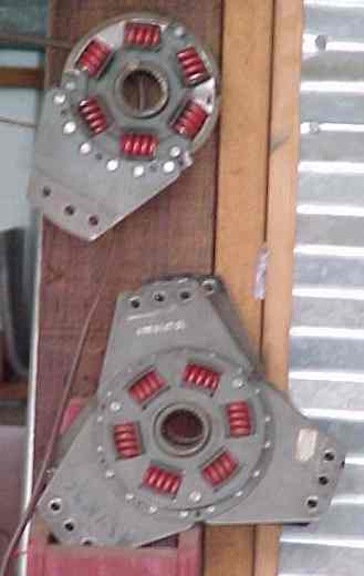
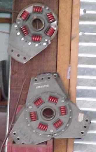
deflect at all. Ross used the springs of a clutch plate with limited
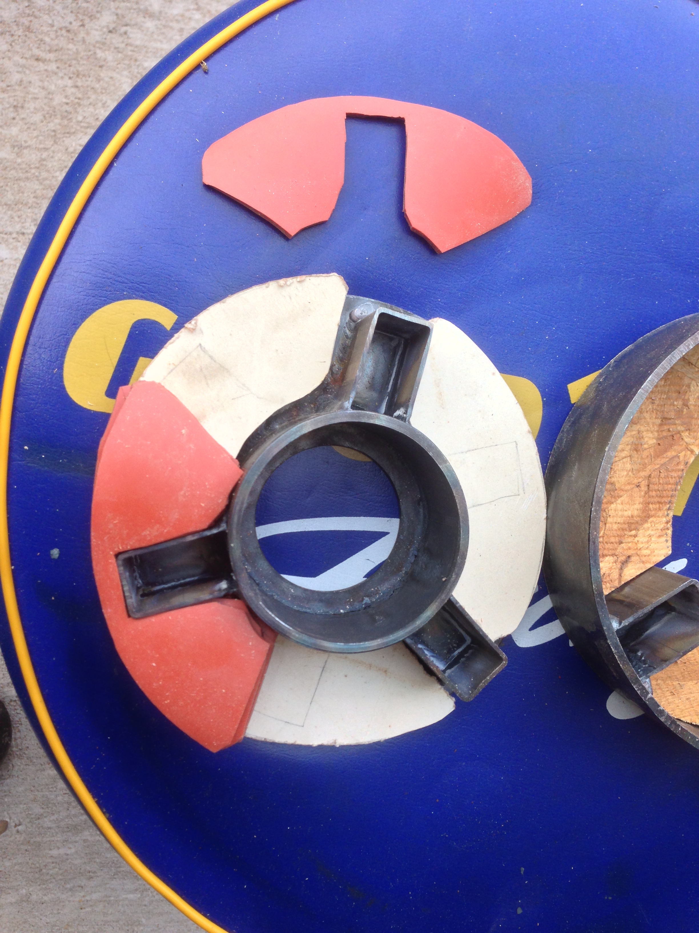
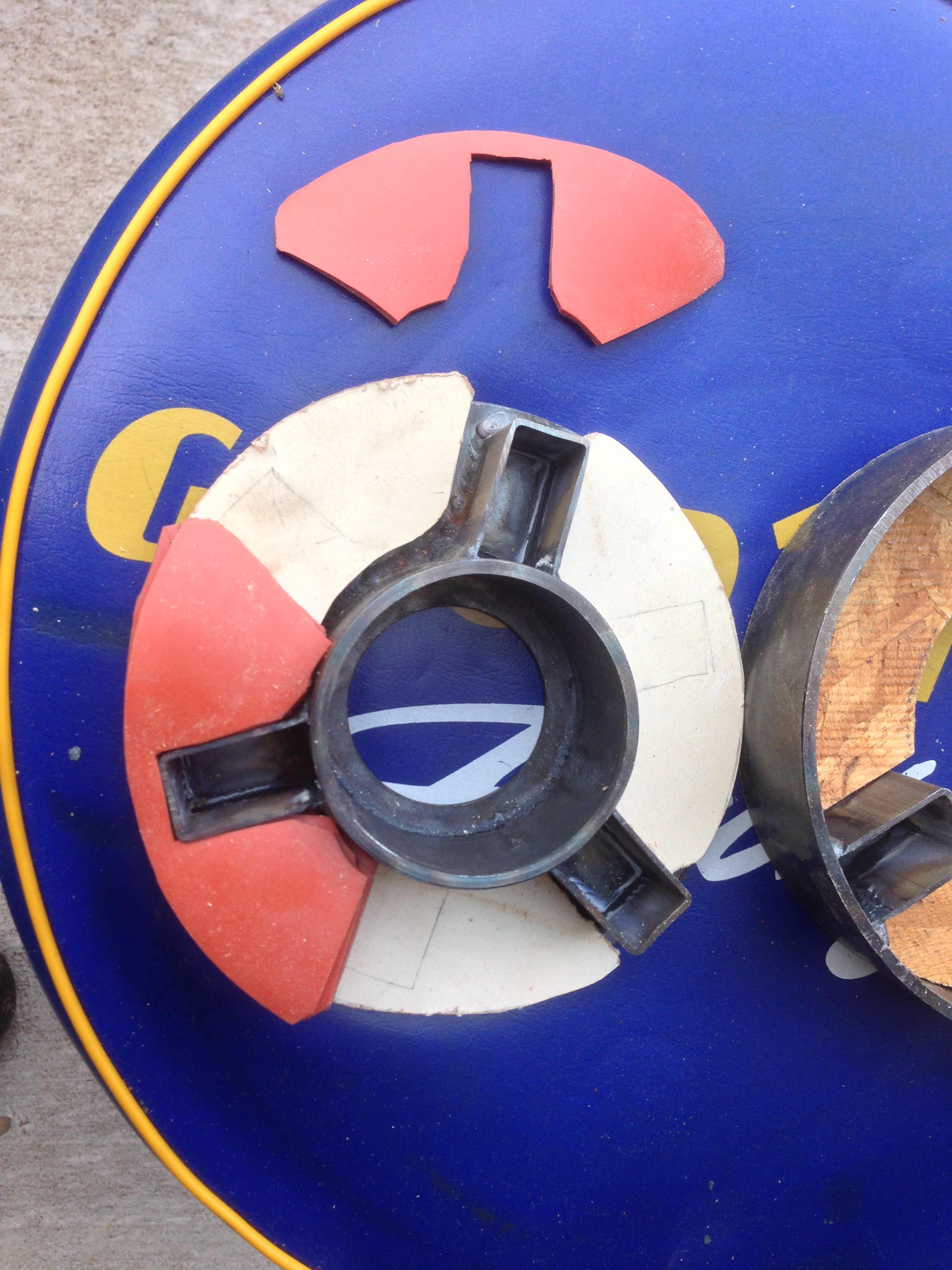
success. Paul has suggested a coupling built with pieces of silicone
rubber, it looks good but as far as I know has not been tested. Tracy
had his own design and wrote clearly about the design process but
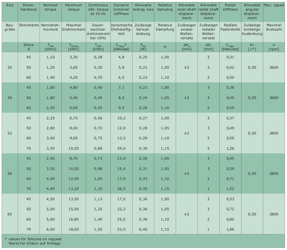
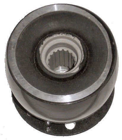
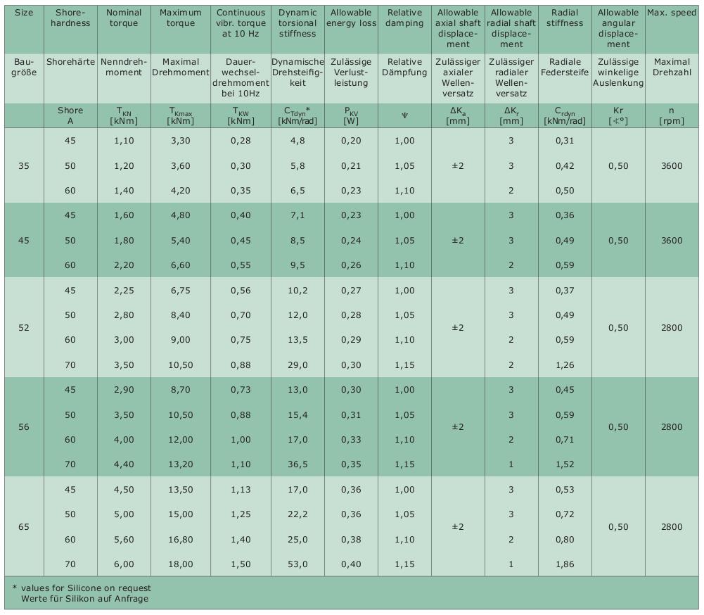
without sharing any of the math. There are commercially available rubber
giubo disks used in many European cars. Tracy called this the "BMW
seduction" but it's also available from Centaflex and commonly used to
solve the same problem in industrial and marine drives. Vassily at
Airtrikes successfully uses Mercedes giubos with his spur gear redrives.
Rotax and Geared Drives (Bud Warren design) use clutches -- Rotax to
decouple when torque gets too high, Geared to not engage until engine
speed exceeds the resonant point. In every case you need to establish
how long something will last in worst case conditions (operating at the
critical resonance point) before something breaks.
I don't use the terms "damper" or "harmonic" because there is no damping
going on, and this is mostly at the fundamental frequency, not a
harmonic. Damping of a resonance requires resistance, in which the
excess energy is dissipated as heat, and that's not happening here. Any
of these devices would burn up in an instant if they were actually
absorbing any significant part of the engine's power. And "dampen" means
to make wet, not attenuate, so it's not a "dampener." An elastomeric
member or spring breaks a resonance by compressing, shifting the
resonant frequency momentarily so the resonant point is no longer where
it was.
My background is in EE and acoustics. I design and make acoustic
transducers for a living, so resonance, damping and compliance are a
little bit familiar. I have studied redrive design for some time (I am
still looking for an engine/redrive that will work for a low speed
propeller design project) and have met a few of the problems, but know
only that I am certainly not an expert in any of this -- but I can now
tell when "expert" opinions aren't supported by physics.
David Josephson
Let me know what you come up with. A lot of people have been fooling with
this for a long time. Gear and spline back lash probably enters in to it and
that changes over time. So too rotor bearing clearance. Two nine pound
rotors have a significant effect on the polar moment of inertia. Prop weight
also varies. Beware of the rotary's high RPM when looking at open rubber
couplings. I think that had something to do with the RotoMax crash.
Then there is the question of shock load
on the gears. Seems like a bit of rubber is called for there. Some Brit
engineer
said "An ounce of rubber is worth a pounds worth of engineering :) Silicone
rubber is tough and high temperature. Ideal for this use.
It seems no matter what we do the resonance happens at 1800 engine RPM.
No problem idling the rotary engine above 1800 RPM as the prop is only
going 600 RPM roughly. I was rather surprised to find the same resonance
RPM on the RotoMax engine with an entirely different gear box, engine
design and coupling.
When I shut off the O-470 in my Cessna 182 the whole airplane
shutters as it passes through resonance RPM.
Paul Lamar
The Rotary Engine News Letter. Powered by Linux.
ACRE NL web site.
http://www.rotaryeng.net
You Tube
http://tinyurl.com/beqqxas
Copyright 1998-2014 All world wide rights reserved.