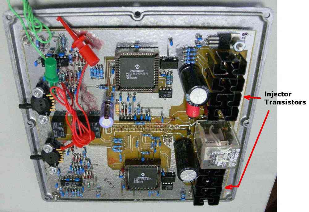
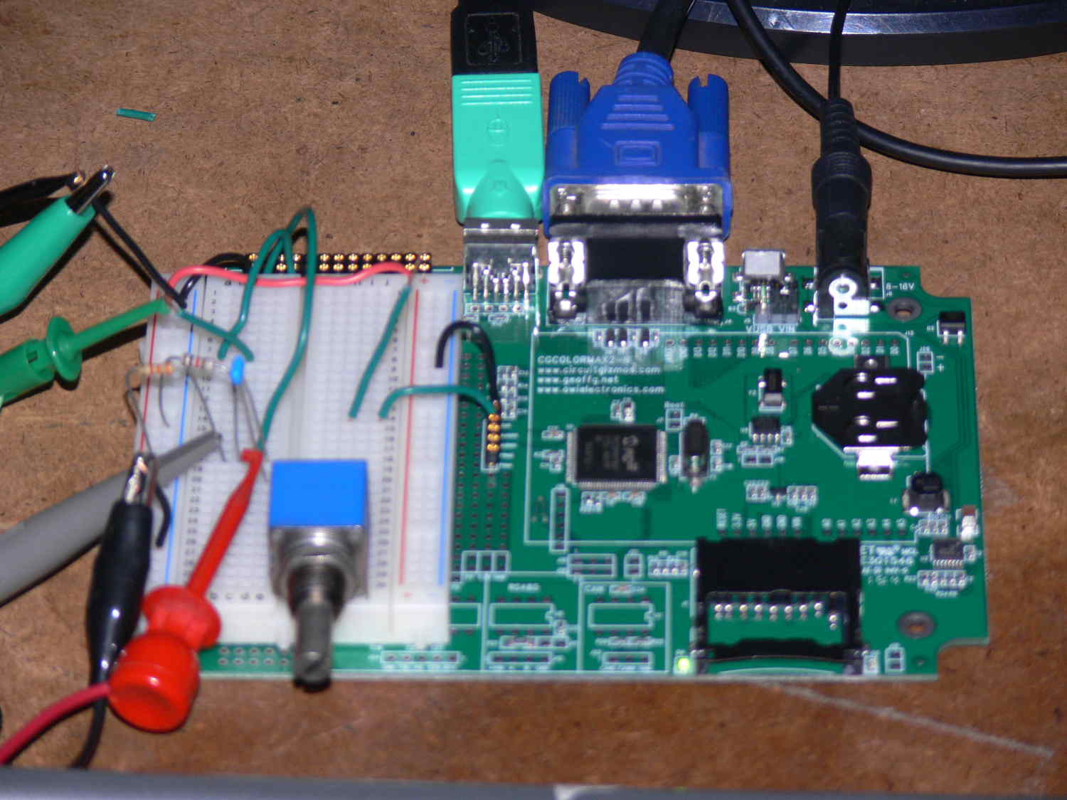
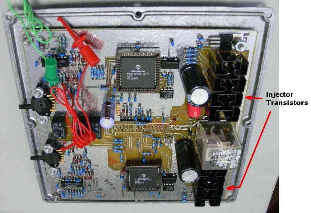
Will control up to four high speed CD systems on plug. It will spark
up to 6 times 5 degrees apart at 10,000 RPM.
Two VR sensors and four optical or Hall Effect triggers are
accommodated.
It will work with existing car computers or stand alone engines with
out EFI computers. It will work with carburettors.
It can be programmed with a wide variety of sparking scenarios. Not
just every 5 degrees. The amount of energy in the spark is also
programmable.
Paul Lamar
Is this project complete, or still prototyping? C. Smith
It is complete.
Paul Lamar
Paul, does this system also control the fuel injection? If not, are you
considering
adding that function because I really want to go fuel injection for
better fuel
economy and to eliminate carburetor icing. Since I live at 8,600 feet
elevation
I will be turbocharging and want a system that will allow leaning for my
high
altitude cruising.
Thanks. Ron Reynolds - Wyoming
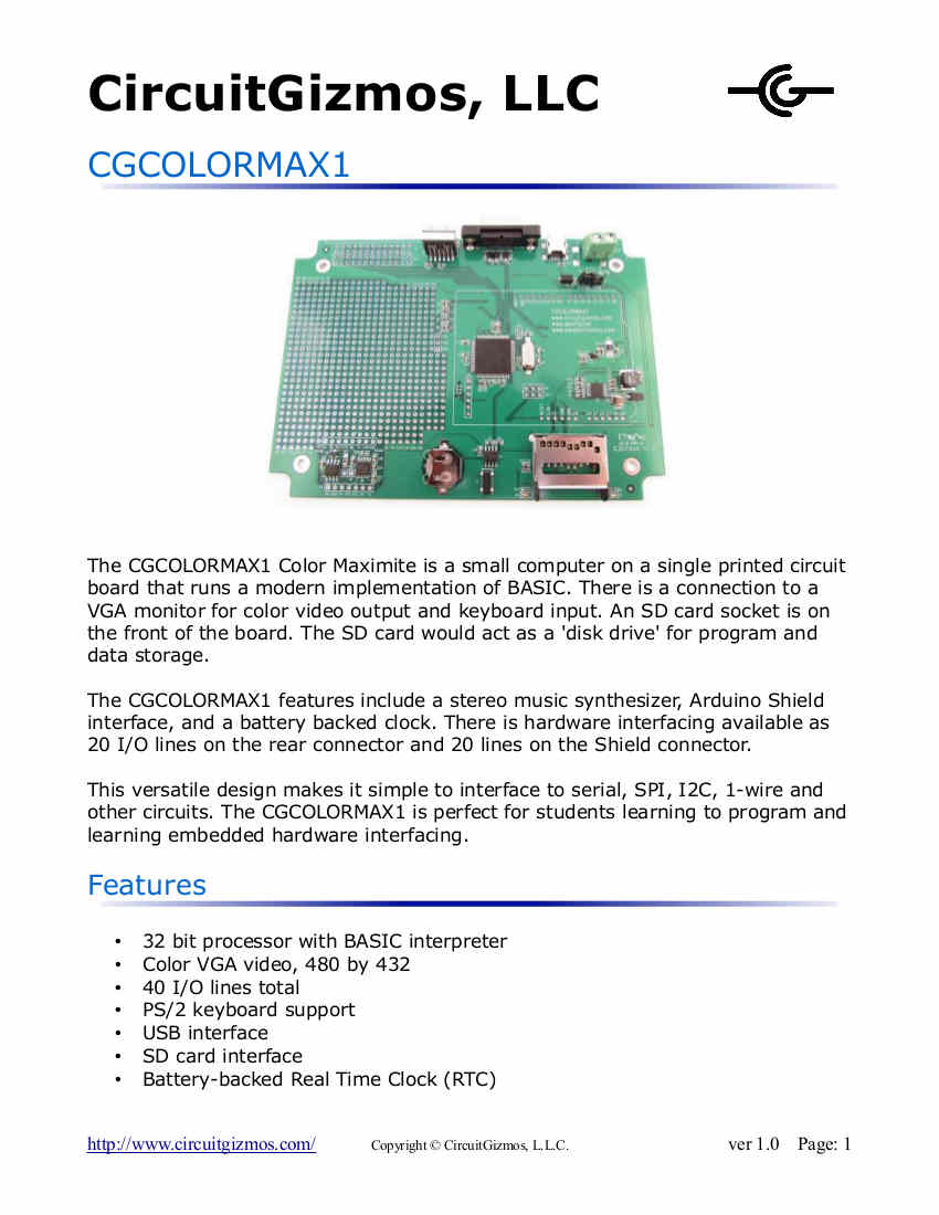
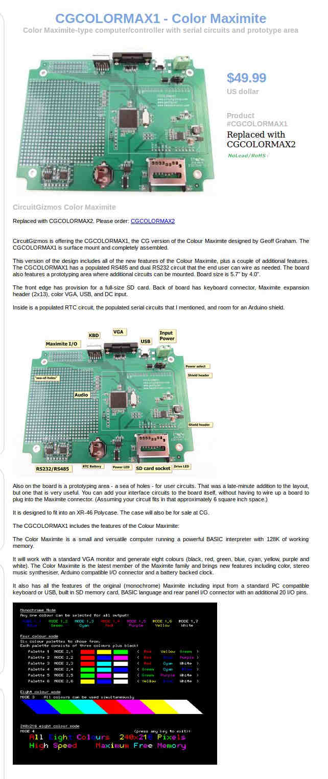
No this one is not designed for fuel injection. The off the shelf Maximite
is the one to use for fuel Injection and EFIS. I hope to have a Maximite
bench demo
working for my forums at Sun N Fun in April. If you do that this control
computer
is not necessary. The Maximite can trigger the ignition CD systems instead.
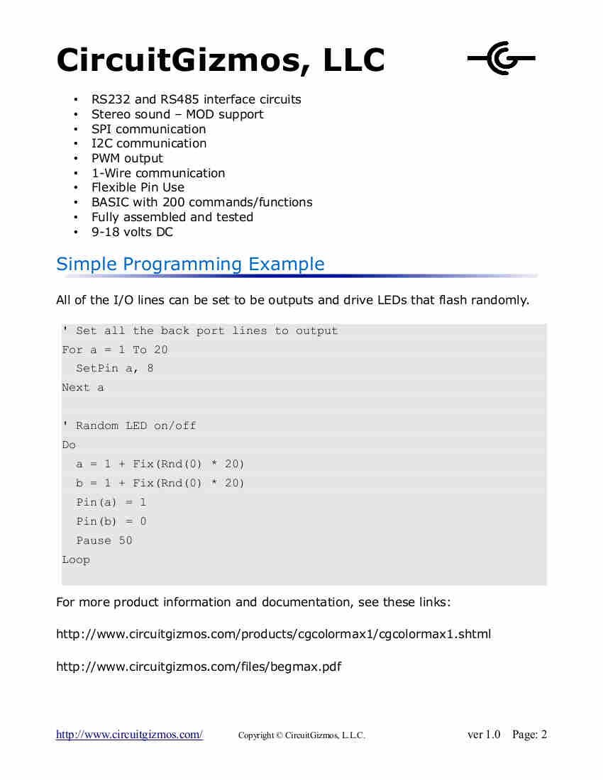
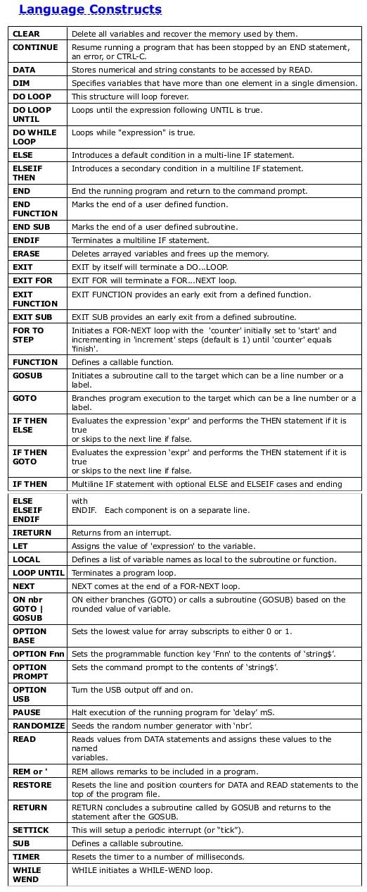
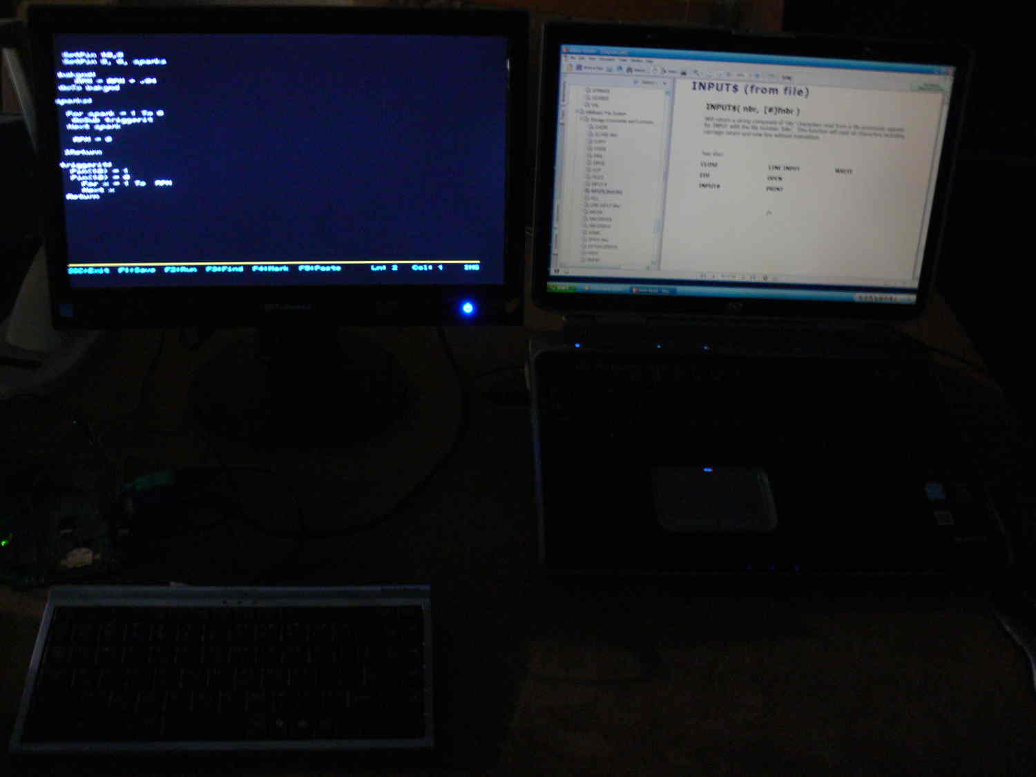
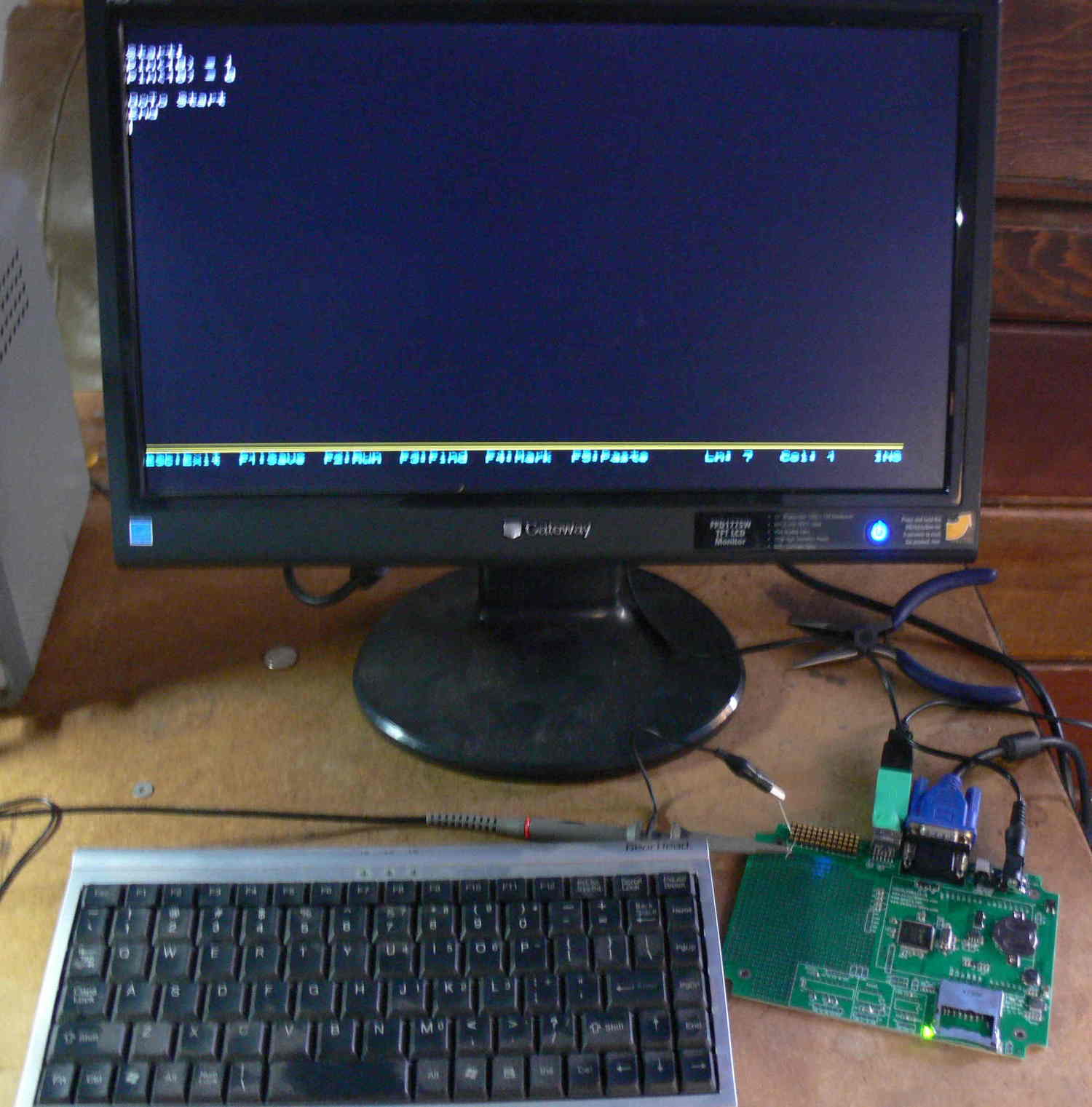
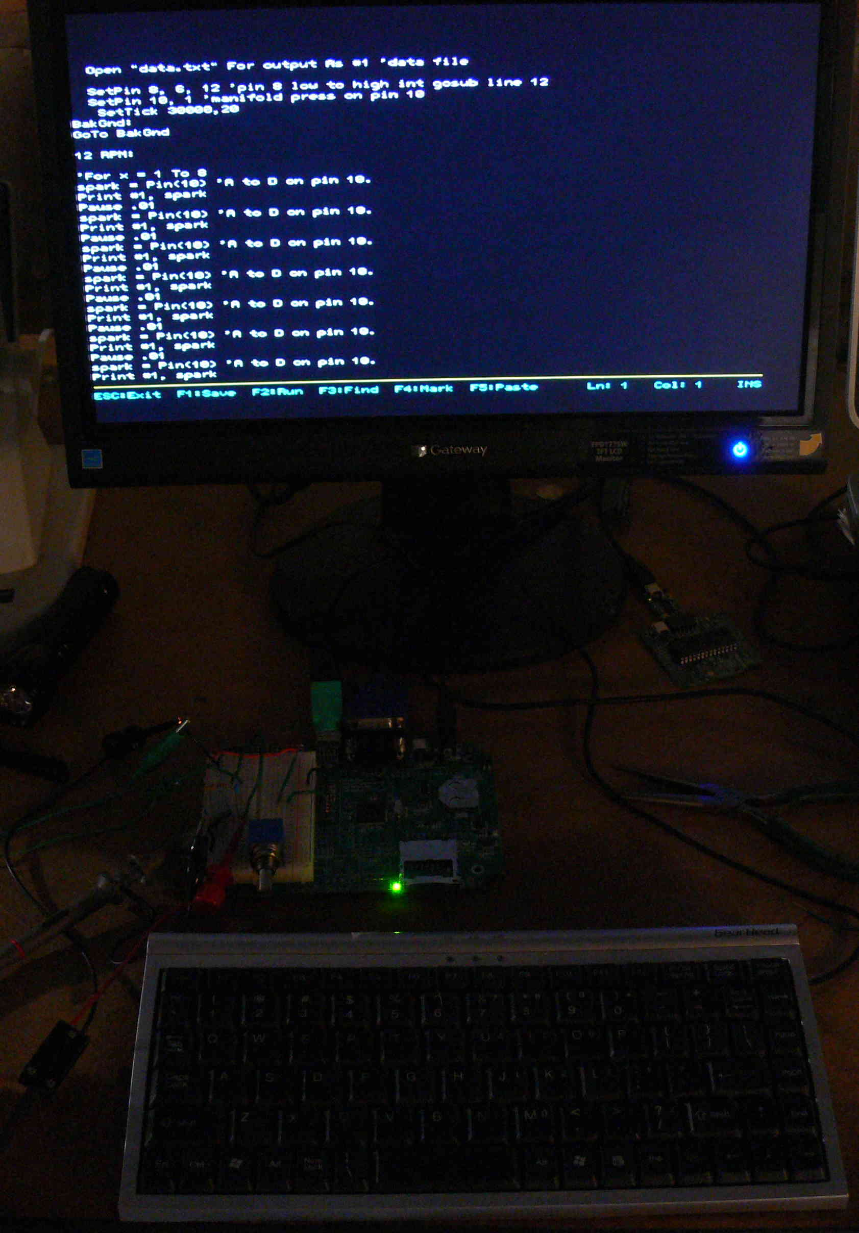
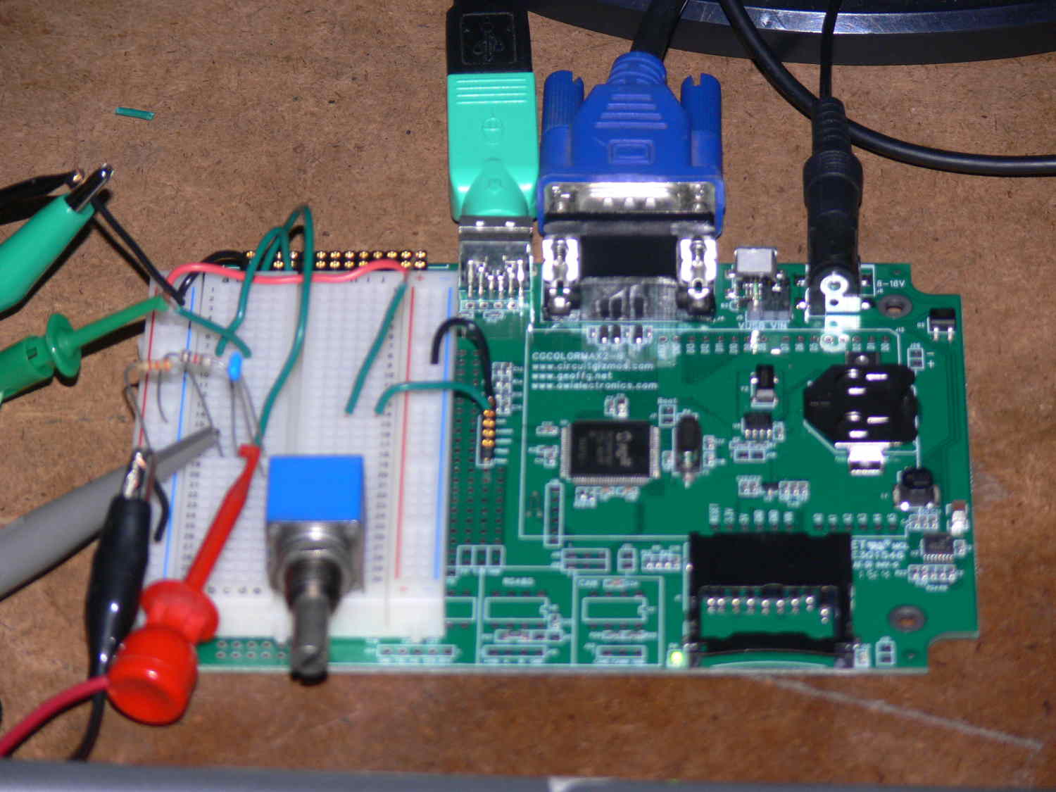
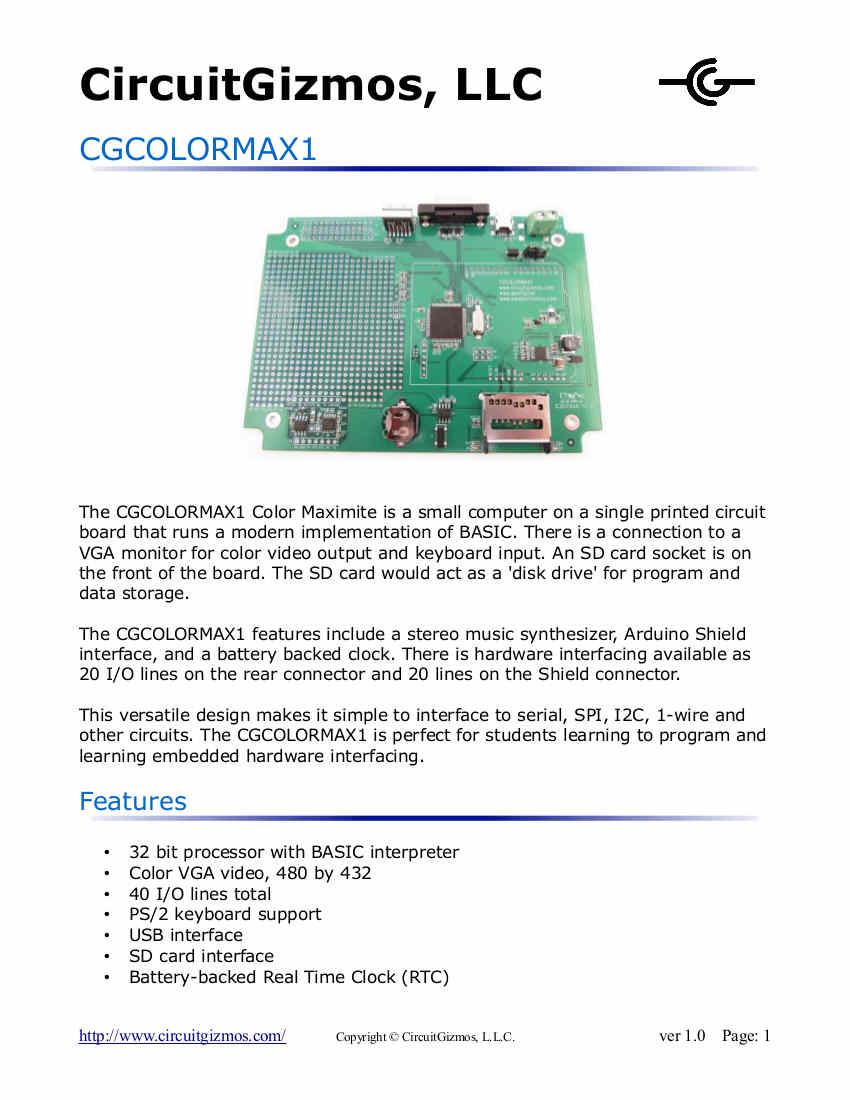
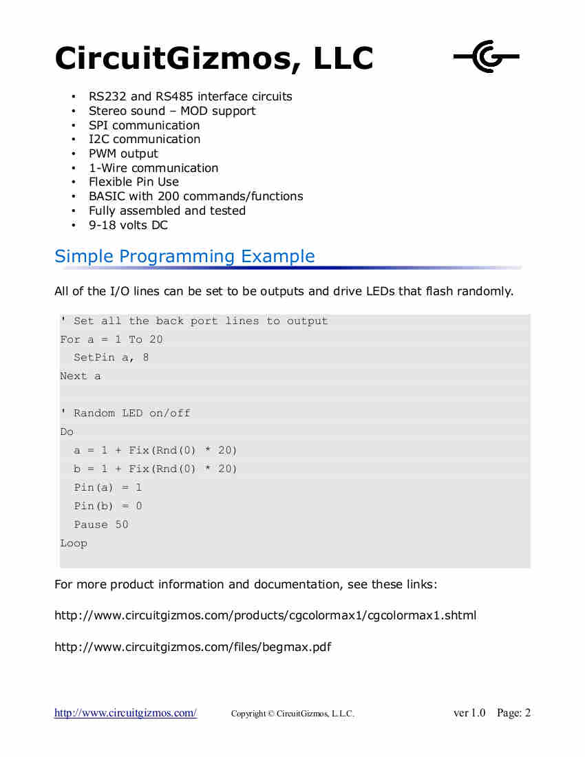
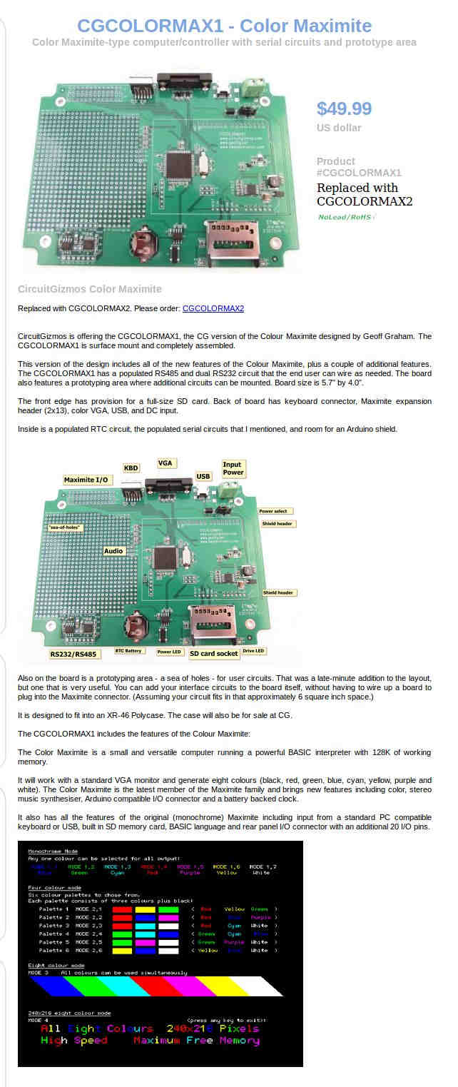
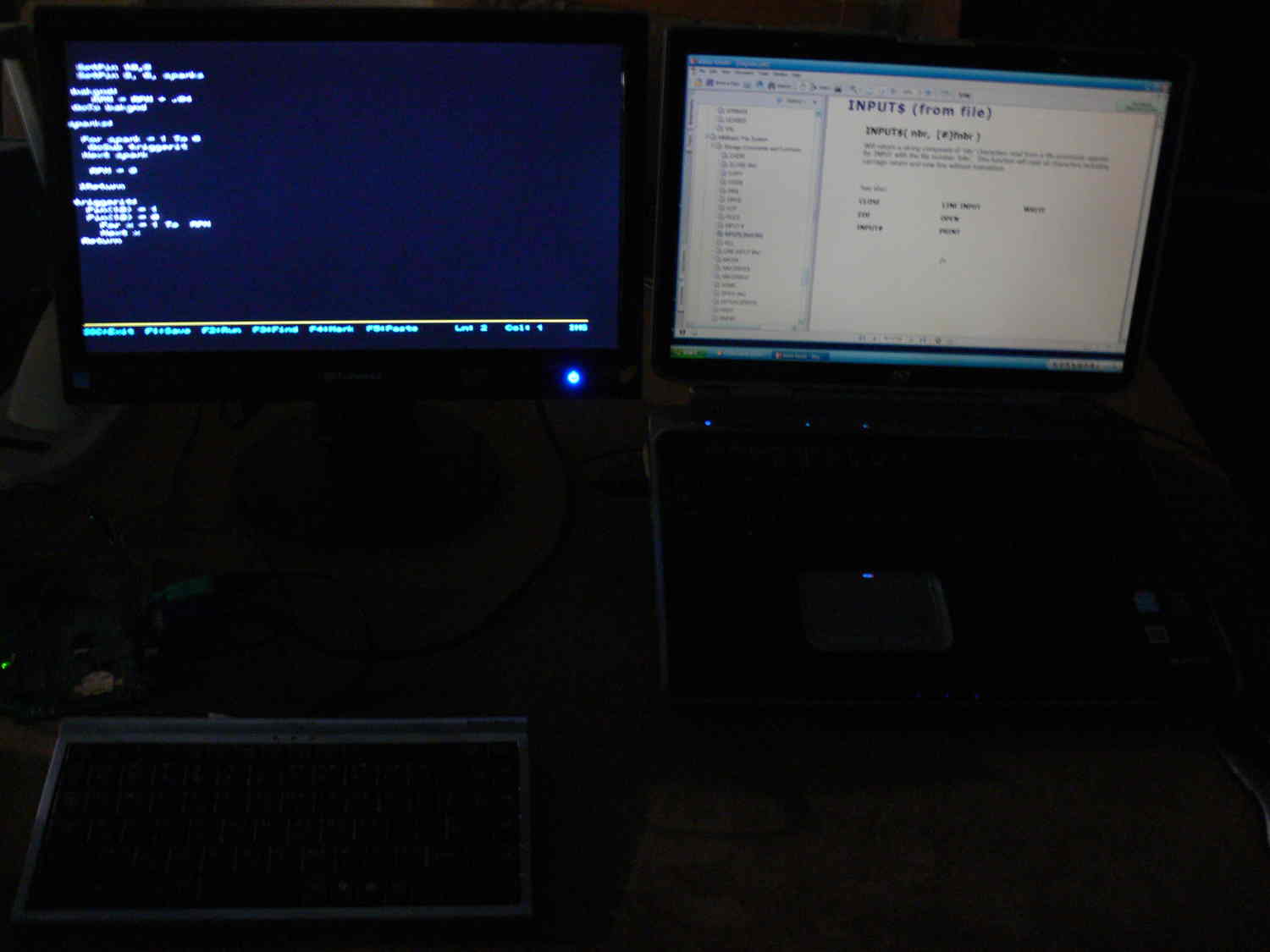
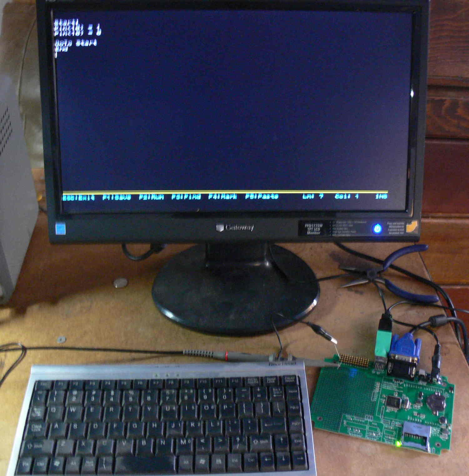
Here is a very simple BASIC EFI/EFIS program that will run on the Maximite.
The Maxmite uses a PC VGA display mounted on the instrument panel and a
PC keyboard.
Ignition is not implemented yet. The 18 meg docs on the Maximite are
free for
download.
There will be a separate small PC board needed with injector drivers,
manifold pressure
and trigger sensor circuits very similar to Tracy's system.
Lines starting with a ' are docs only. Not part of the program.
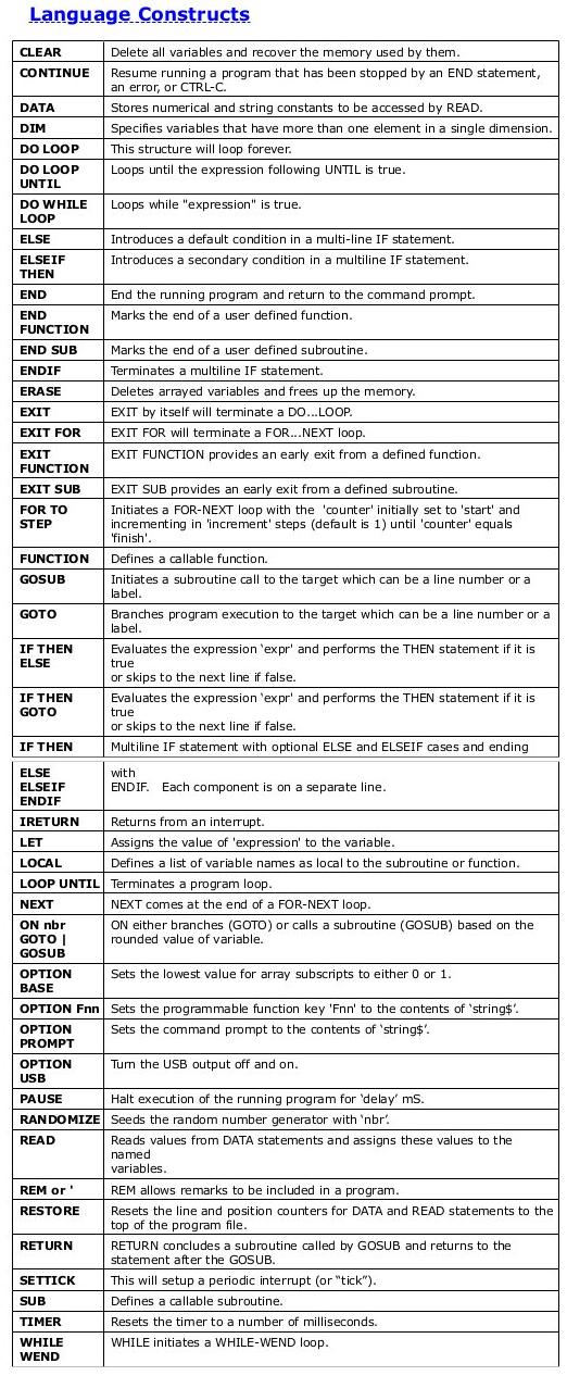
'SETPIN pin, cfg [,target]
'Will configure the external I/O pin according to cfg :
'The original Maximite has 20 I/O pins numbered 1 to 20, the Color
Maximite adds
'another 20 I/O pins on the Arduino connector. These are labeled D0 to
D13 and A0
'to A5.
'0 Not configured or inactive
'1 Analog input (pins 1 to 10, A0 to A5)
'2 Digital input (all pins and 5V tolerant on pins 11 to 20)
'3 Frequency input
'4 Period input
'(pins 11 to 14)
'(pins 11 to 14)
'5 Counting input
'(pins 11 to 14)
'6 Interrupt on low to high input change (pins 1 to 20, D0 to D8) for
target
'7 Interrupt on high to low input change (pins 1 to 20, D0 to D8) for
target
'8 Digital output
'(all pins)
'9 Open collector digital output to 5V (pins 11 to 20, D0 to D13) In
this mode the
'function PIN() will also return the output value.
'The starting line number of the interrupt routine is specified in the
third 'parameter
' target . This mode also configures the pin As a digital input so the
value of the 'pin
'can always be retrieved using the function PIN().
'See also IRETURN to return from the interrupt.
'See also:
'IRETURN PORT P
"The program starts here.
Mode 1
'Mode # changes the size of the characters on the display.
For n = 11 To 20
SetPin n, 9 'set pins 11 to 20 as open col 5 v output
Next n
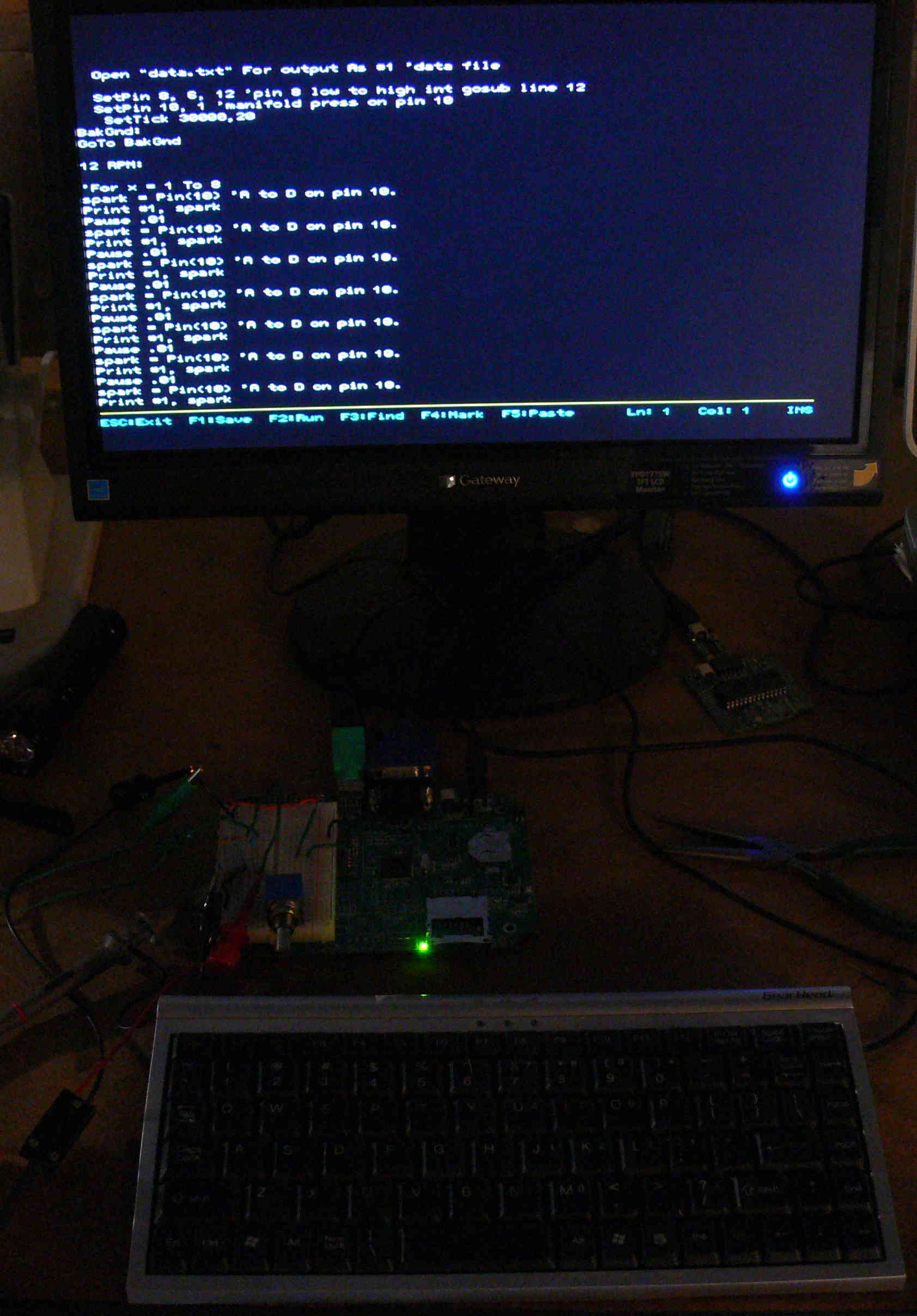
Open "data.txt" For output As #1 'data file
SetPin 8, 6, 10 'pin 8 low to high int gosub line 10
SetPin 10, 1 'manifold press on pin 10
SetTick 1000,20
BakGnd: 'loops over and over again
manpre = Pin(10) 'A to D on pin 10. may need to be scaled
manpre2 = manpre * 10
manpre3 = Int(manpre)
PWM 20,manpre3,manpre3
'pulse width on primary injectors
'and secondary 20 times a second
'as a function of manifold pressure
GoTo BakGnd
10 RPM:
RPM = RPM + 1
IReturn
20 RPMRoutine:
RPM=RPM*30
Cls
Locate 30,30
Print "RPM = ";RPM
RPM = 0
Locate 30,60 'col 30 line 40
Print "Manifold pressure = ";manpre 'EFIS function
IReturn
'There is no copyright on this code. It is open source. Everything
learned will
'be shared.
Paul Lamar
The Rotary Engine News Letter. Powered by Linux. ACRE NL web site.
http://www.rotaryeng.net/ You Tube
http://tinyurl.com/beqqxas
Copyright 1998-2015 All world wide rights reserved.