This is a 2" by 6" aluminium extrusion about 4 inches long. This is
very similar to what I am doing with the ignition stuff so I am all
set up to machine the covers.
There is an aux board the same size as the MM board mounted below the
MM.
So far there are two VR sensor circuits and eight high current
drivers for four coils and four injectors on the aux board. The next
thing on the aux board will be two manifold pressure sensors. One for
the front rotor and one for the rear.
The back panel has the connectors for the VGA, the PC keyboard, the
USB connector and the 12 VOLT power connector.
The front panel will have two DB15's one for output and one for
input. Also a slot for the 65 gig SD card.
So far all through hole.
-----------------------------------------------------
Here is my latest iteration of the PC board. I added an RS232 9 pin
D-sub-min. Matt Boiteau is using that.
The surface mount manifold pressure sensors are on the right, 29 psi
so this board will work with turbo's. I am thinking of adding EGT
sensor circuits.
EGT sensors respond slowly so It mind be possible adjust the mixture
in cruise.
Of course they could be displayed on the EFIS part.
Anybody have any other things they would like added?
I should have this running on the RV4 in a few weeks.
Paul Lamar
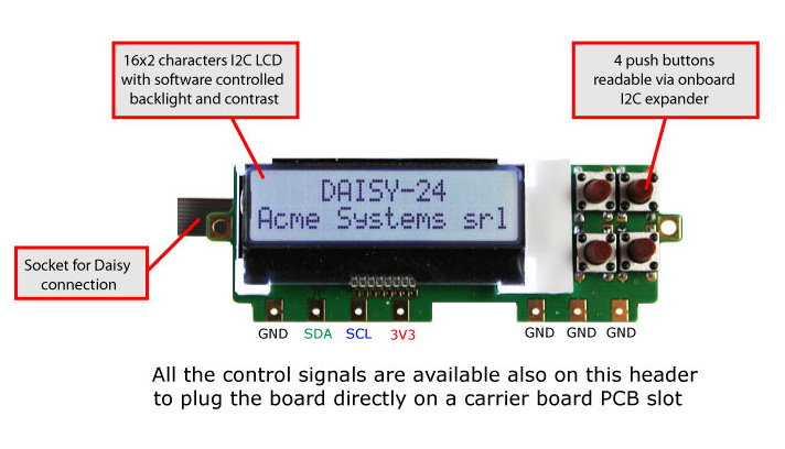
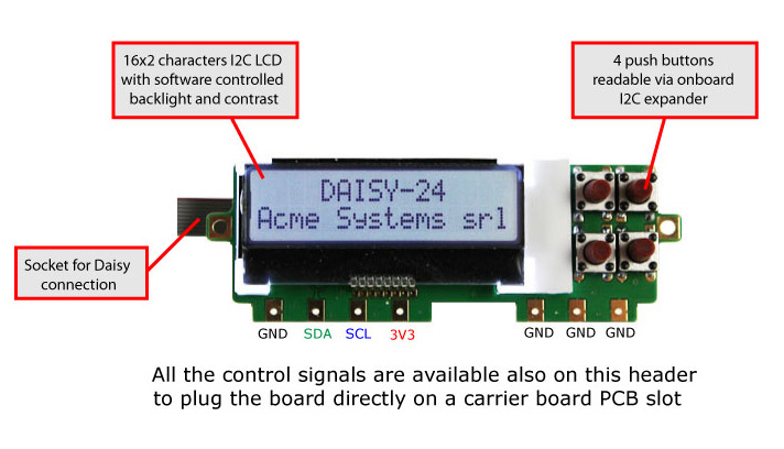
What about the 20 shield i/o pins, too add LCD screen with push buttons?
Do 2 DB25's, to cover all the 40 i/o ?
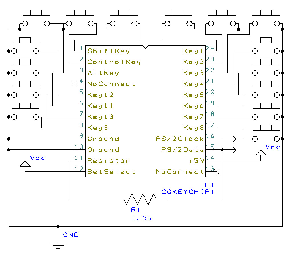
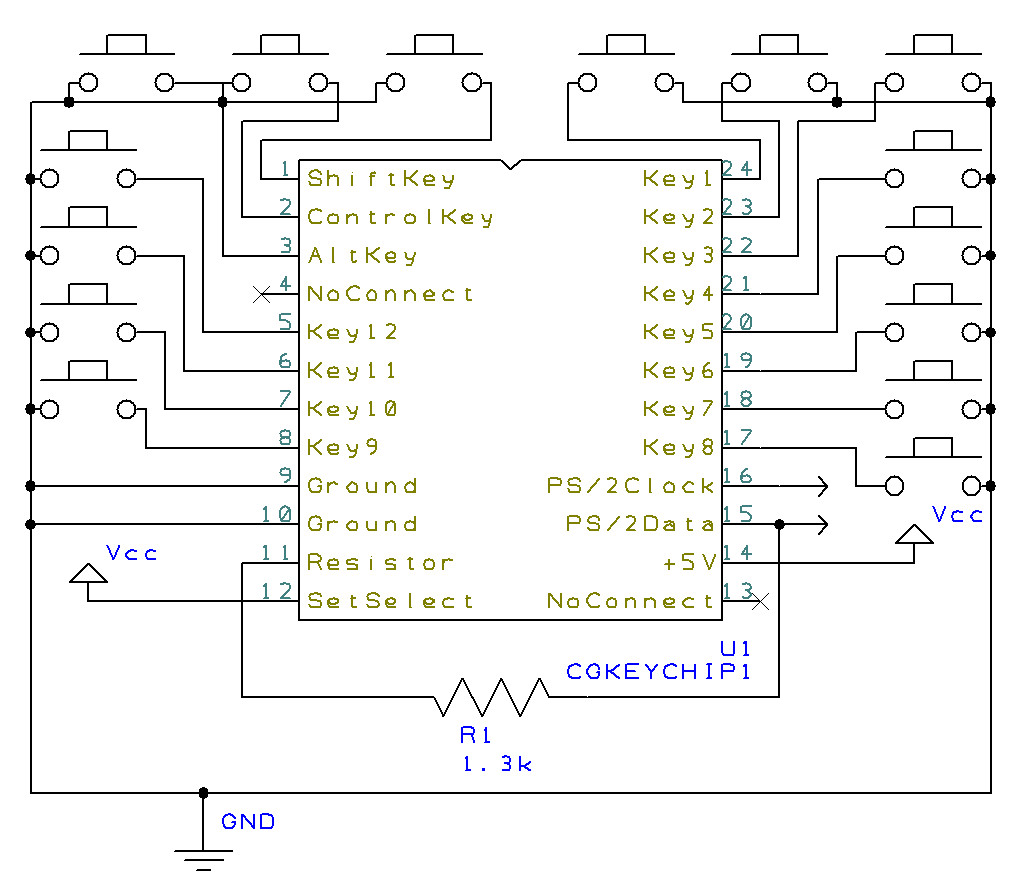
I bought the custom keyboard chip , so I have the option of wiring in 12
distinct push buttons instead of using 12 i/o pins.Maybe at the back put
another DB25, and the user can wire that up to anything he wants on the
inside.
http://www.circuitgizmos.com/products/cgkeychip1/cgkeychip1.shtml
I can see this project turn into an LCD screen to display EIS sensors and
engine running software. Have push buttons below LCD screen to change
programs on the fly, run user functions from the maximite (cold startup,
cycle coil packs for run-up tests, etc), acknowledge errors,anything we can
think of.
The analog inputs can only handle up to 3.3Volts. Basic voltage divider
will fix that. Have you done any sensor inputs yet? (MAF, Crank position
sensor, etc?) I don't want to reinvent the wheel if you have something
working for analog inputs circuitry.
I'm just starting to play around reading a temp sensor gauge. Slow start,
lots of learning how to interface with this board and computer first. I can
make an LED turn on.. lol.
-Matt
- Matt
Why would you want a a small LCD screen when you have a full
VGA display to work with. Since the VGA is memory mapped it is likely
faster than sending characters one character at a time to a LCD screen.
This is a major milestone in control computers.
Paul Lamar
The Rotary Engine News Letter. Powered by Linux. ACRE NL web site.
http://www.rotaryeng.net You Tube
http://tinyurl.com/beqqxas
Copyright 1998-2015 All world wide rights reserved.