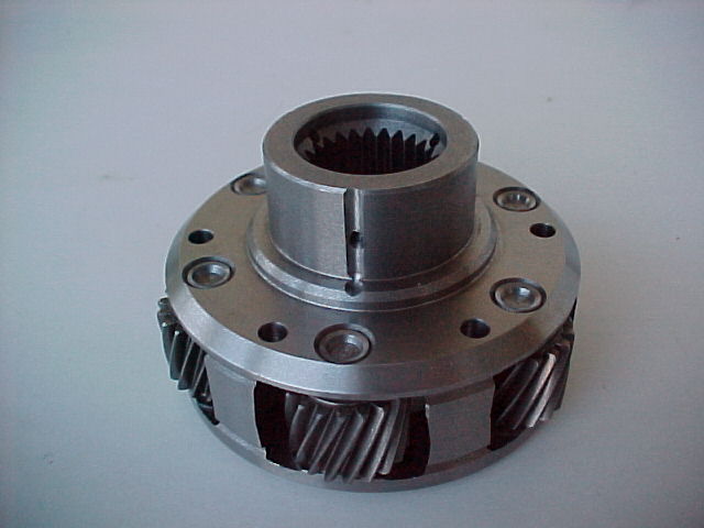
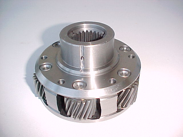
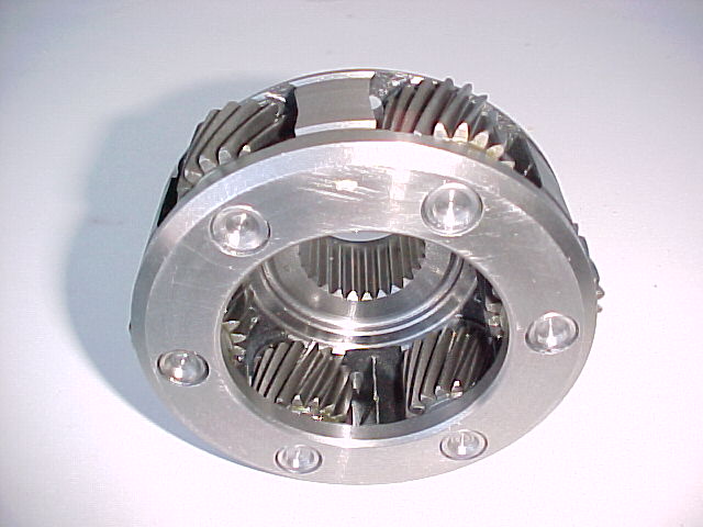
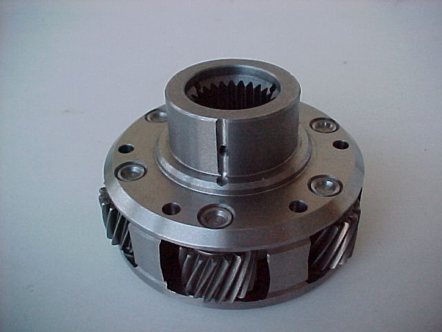
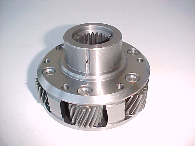
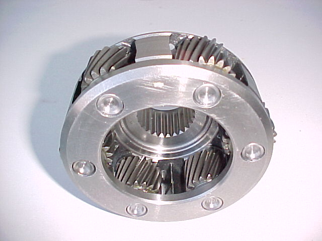
Chris, your 2.85 gear set is in. Will be mailing it shortly.
Here also is a size comparison of the 2.85 front planet with the 3.12
rear planet.
Paul Lamar
Hi Paul,
Looks good, does it have the splined drive boss on it for the prop
shaft, I couldn't tell from the pictures.
Cheers Chris.
Not the way I would do it but yes it has aluminium female splines.
http://www.engineeringtoolbox.com/torsion-shafts-d_947.html
Shear Stress in the Shaft
When a shaft is subjected to a torque or twisting, a shearing stress is
produced in the shaft. The shear stress varies from zero in the axis to
a maximum at the outside surface of the shaft.
The shear stress in a solid circular shaft in a given position can be
expressed as:
τ = T r J (1)
where
τ = shear stress (MPa, psi)
T = twisting moment (Nmm, in lb)
r = distance from center to stressed surface in the given position
(mm, in)
J = Polar Moment of Inertia of an Area (mm^4 , in^4 )
Note
the "Polar Moment of Inertia of an Area" is a measure of a shafts's
ability to resist torsion. The "Polar Moment of Inertia" is defined with
respect to an axis perpendicular to the area considered. It is analogous
to the "Area Moment of Inertia
<http:www.engineeringtoolbox.comarea-moment-inertia-d_1328.html>" -
which characterizes a beam's ability to resist bending - required to
predict deflection and stress in a beam.
"Polar Moment of Inertia of an Area" is also called "Polar Moment of
Inertia", "Second Moment of Area", "Area Moment of Inertia", "Polar
Moment of Area" or "Second Area Moment".
Circular Shaft and Maximum Moment
Maximum moment in a circular shaft can be expressed as:
T_max = τ_max J R (2)
where
T_max = maximum twisting moment (Nmm, in lb)
τ_max = maximum shear stress (MPa, psi)
R = radius of shaft (mm, in)
Combining (2) and (3) for a solid shaft
T_max = (π 16) τ_max D^3 (2b)
Combining (2) and (3b) for a hollow shaft
T_max = (π 16) τ_max (D^4 - d^4 ) D (2c)
Circular Shaft and Polar Moment of Inertia
Polar Moment of Inertia of a circular hollow shaft can be expressed as
J = π (D^4 - d^4 ) 32 (3b)
where
d = shaft inside diameter (mm, in)
Diameter of a Solid Shaft
Diameter of a solid shaft can calculated by the formula
D = 1.72 (T_max τ_max )^13 (4)
Torsional Deflection of Shaft
The angular deflection of a torsion shaft can be expressed as
θ = L T (J_G) (5)
where
θ = angular shaft deflection (radians
<http:www.engineeringtoolbox.comradian-d_942.html>)
L = length of shaft (mm, in)
G = modulus of rigidity
<http:www.engineeringtoolbox.commodulus-rigidity-d_946.html> (Mpa, psi)
The angular deflection of a torsion solid shaft can be expressed as
θ = 32 L T (G π D^4 ) (5a)
The angular deflection of a torsion hollow shaft can be expressed as
θ = 32 L T (G π (D^4 - d^4 )) (5b)
The angle in degrees
<http:www.engineeringtoolbox.comradian-d_942.html>
can be achieved by multiplying the angle θ in radians with 180 π
Solid shaft (π replaced)
θ_degrees ≈ 584 L T (G D^4 ) (6a)
Hollow shaft (π replaced)
θ_degrees ≈ 584 L T (G (D^4 - d^4 ) (6b)
Bottom line hollow shafts of large diameter are lighter in weight.
If you bolt the planet carrier to a flange welded to a 2 inch OD 3/16 wall
4130 shaft you wind up with the lightest configuration with no back
lash in the spline to worry about.
Paul Lamar
The Rotary Engine News Letter. Powered by Linux.
ACRE NL web site.
http:www.rotaryeng.net You
Tube
http:tinyurl.combeqqxas
Copyright 1998-2015 All world wide rights reserved.