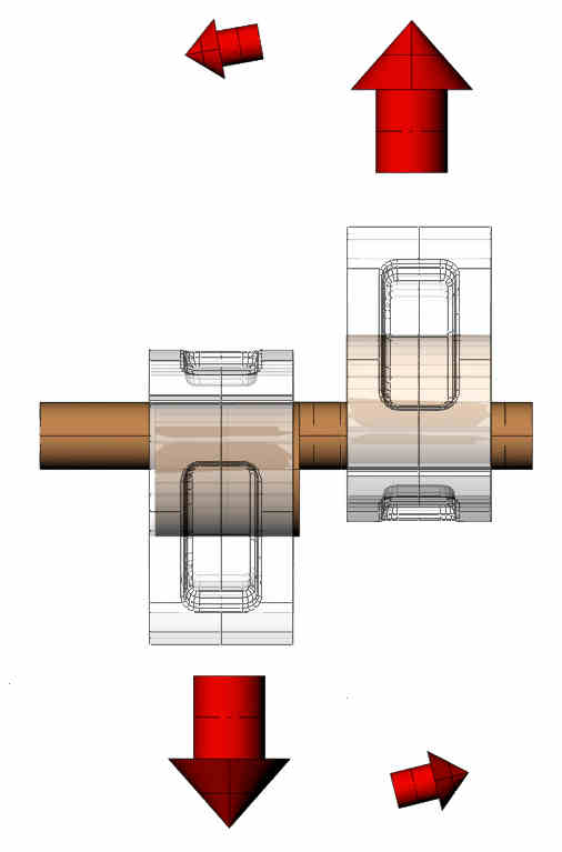
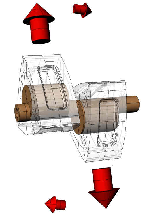
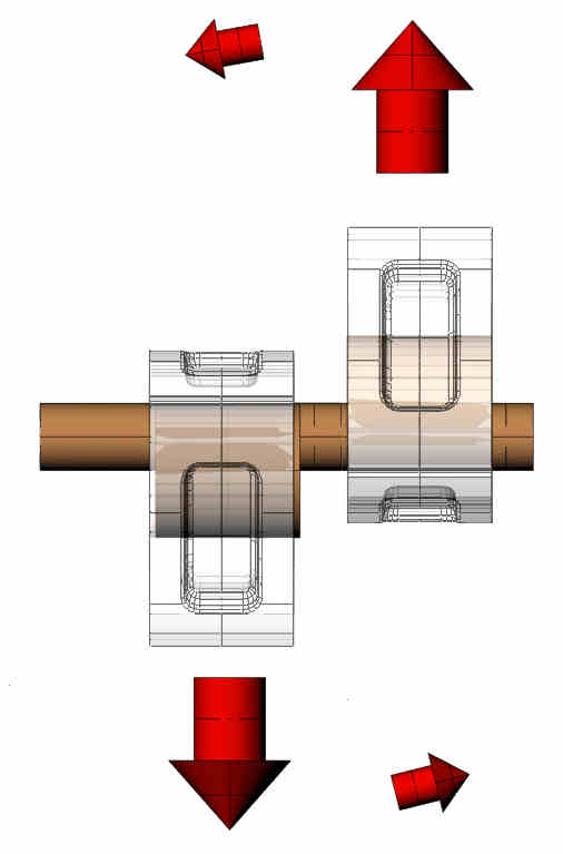
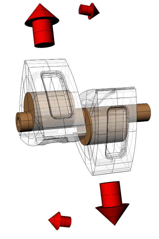
Centrifugal force of a rotating object is MVVR. Where V is the
velocity, and R the radius and M is mass.
This means that unless C.G. is matched exactly, it is impossible to
ballance the engine at different speed.
Fortunately, I think the C.G. Of the rotor travels in a circle.
Therefore it is van be balanced by a weight at the C.G. path of the
rotor. The same goes for the imbalance of the eshaft.
Since counter weight is located only at the end of the engine, I
think you will get from limited twisting on the shaft.
That's IMHO. No guarantee on accuracy.
Henry Nee
Hi,
Can you please explain the problem and solution of balancing when
using a cut down e-shaft with single rotor 1/2 Mazda 13b engine.
Regards Zahid
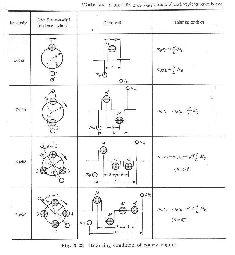
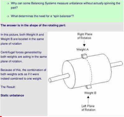
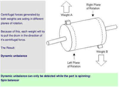
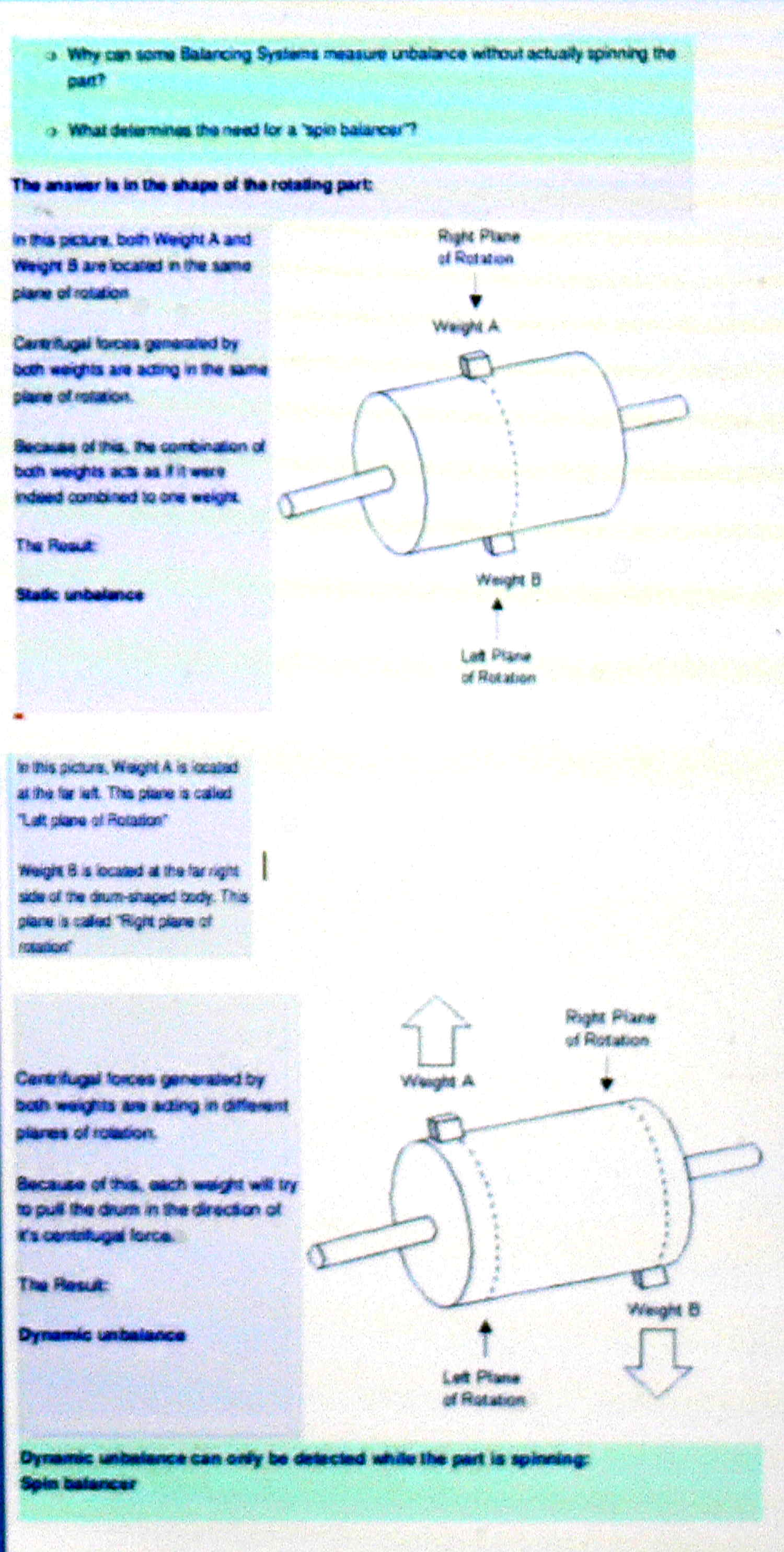
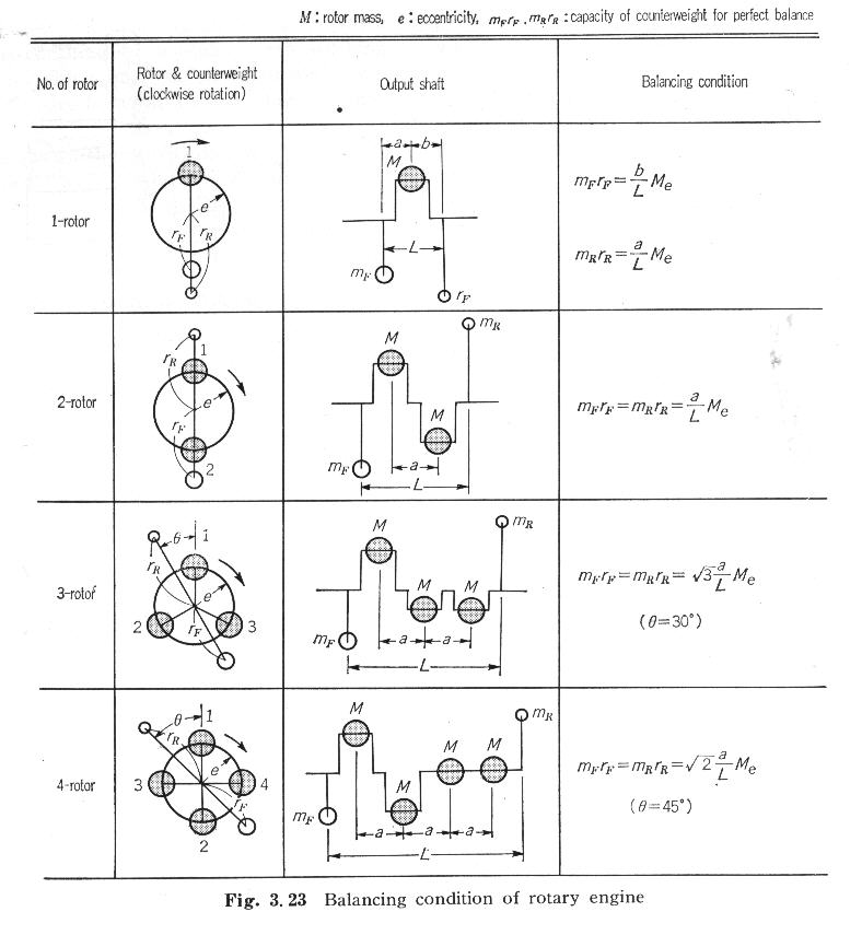
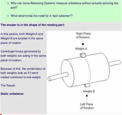
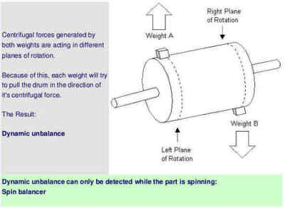
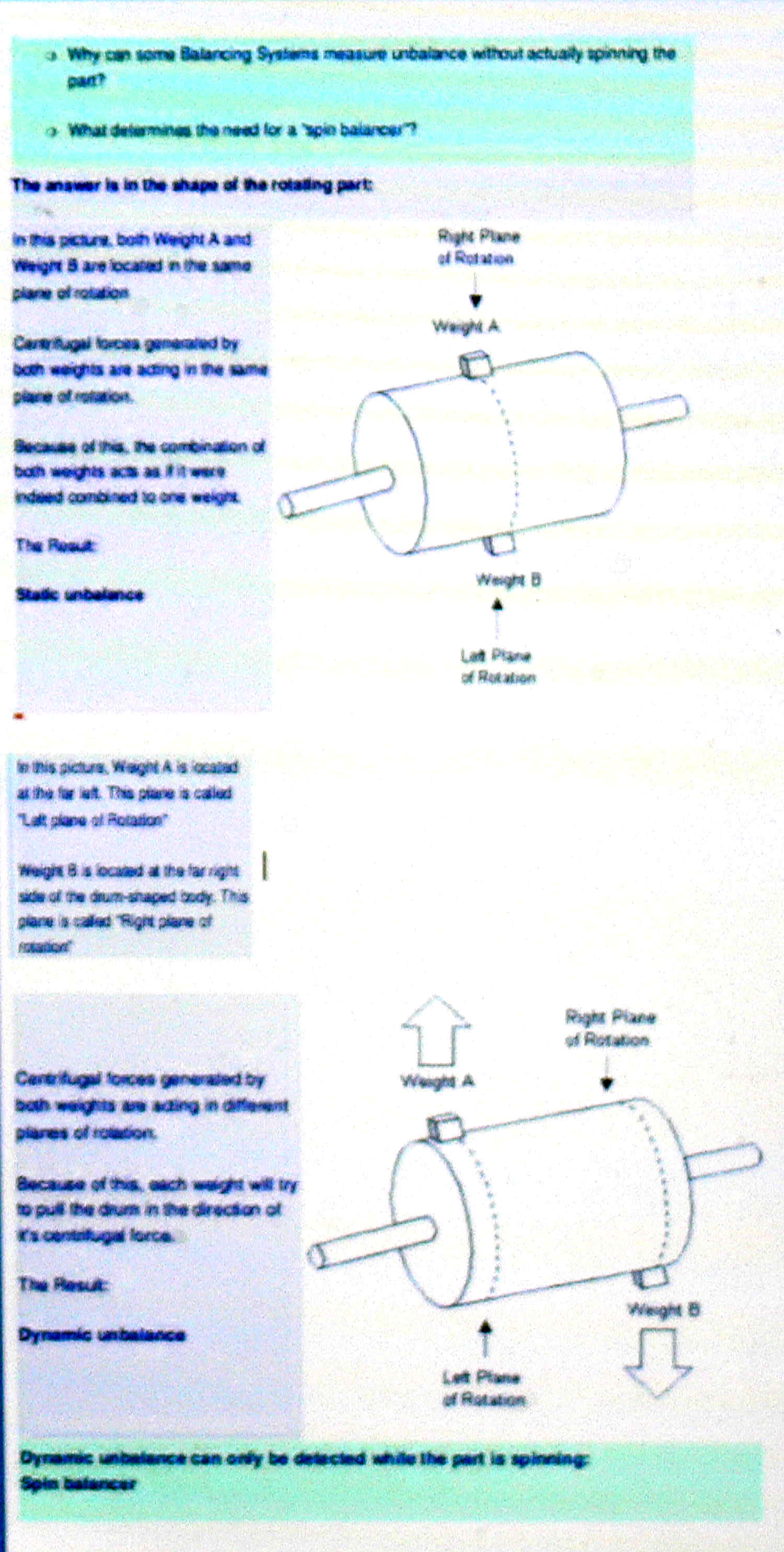
Balance is controlled by these equations. The Wankel is not just
statically balanced but dynamically balanced as well.
In a single rotor engine the counterbalance weights must provide a
STATIC balance for the e-shaft eccentric and its rotor and must also
account for the DYNAMIC wobble caused because the static counter
weights are not located at the mechanical centres of the rotor and
the eccentric. It is impossible to do this.
They must be mathematically sized relative to their lateral position
from the rotor and eccentric centre line.
Paul Lamar
the Tracy ISO is physically attached to the flywheel. Does that need
to be brought in to balance equation as extra mass to mF (front
counter weight) or mR (mass Rear Counterweight)?
Regards Zahid
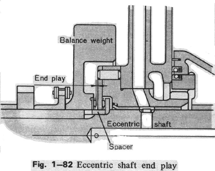
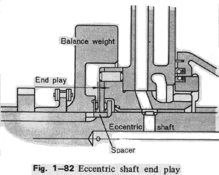
The rear counter weight is hiding behind the ISO.
Paul Lamar
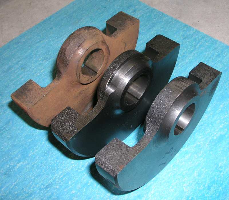
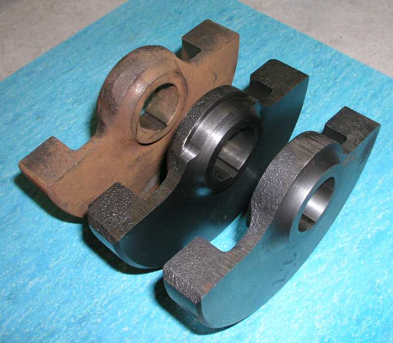
Here is how I solved some of the balancing issues. There are a whole
lot of issues interacting when building a new engine configuration.
Weight control influences almost everything. A single rotor engine
certainly requires a considerable flywheel, if one wants the idle
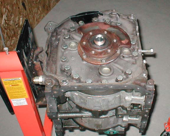
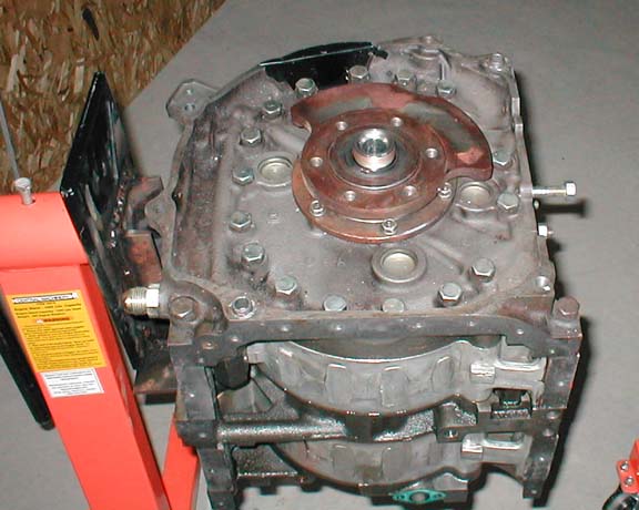
speed somewhere below 3000 RPM. I integrated the rear balance weight
in the flywheel (picture). The front balance weight I modified with
tungsten inserts before dynamic balancing. I ended up with a clean
rotating setup. My engine is based on 12A rotor and housing, so I do
not have any direct comparison to 13B size parts. FWIW.
Richard Sohn N2071U
http://www.fairpoint.net/~res12/home.html
Hi Richard, I have read some postings where some have machined a
single rotor eccentric shaft from a 2 rotor unit. Paul mentions the
shaft needs to be hardened after machining. Could you give a overview
of the process you used to build your shaft ?
Thanks, Steve Carlisle
Here is what I did.
On the first e-shaft I concerted, I left the oil pump side of the
shaft with the front lobe unchanged. After machining the rear end of
the shaft to my mods, I only had one bearing surface to create. I
picked an inner ring of a INA needle bearing with an outer diameter
the same as the original MAZDA bearing, and pressed it on the shaft.
As it turned out, it was a solution, which never failed during all
the ground testing of the first engine I build, with a run time of
around 50hrs. I did not consider this a solution for a final, flyable
configuration. The solution I have in the engine now is a case
hardened bearing section. The biggest problem was finding someone for
the case hardening and grinding who was willing to do it for and
affordable cost. FWIW
Richard Sohn N2071U
http://www.fairpoint.net/~res12/home.html
I misunderstood the last email by Richard Sohn. He was referring to
case hardening process for e shaft . I thought he was referring to
case hardening for bearing. So please do not publish my last email.
Zahid Rahman
I am thinking, since the rotor rotates at one third the speed of the
esfaft. One needs a 3:1 reduction gear on the counter weight to
matched the rotor's rotation speed.
Corrections welcome!
Henry Nee
I'm not sure at all, but you have to compensate for the weight that
is centered in the shaft eccentric, and this rotates at shaft speed.
Or not? Thanks. Best regards. Salut † Jose Gros-Aymerich Madrid,
Spain
Yes, I believe you need two counter weights. One rotates at reduced
speed to balance the rotor, and a second one in same speed with the
eshaft.
That's why two rotors is much better balanced.
Henry Nee
Guys/Gals,
Read the post that Paul put up today at 13:15. The motion of the rotor
has nothing to do with the required balance weight attached to the
E-shaft. No reduced speed, no increased speed, just E-shaft speed.
Mark LaPierre
Mark,
Just want to be a little clearer. As I have been mislead before and I
would like to make it clear what the balancing is on, and hopefully
others don't make the same mistake I did before.
To start, I'd like to retract my opinion that there needs to be a speed
reduction of 1:3. After studying it more, I notice that the C.G of the
Rotor, does travel at the same rpm as the eshaft.
Let me explain. I think we need to balance two things.
1. The Eshaft
2.The orbital rotation of the rotor (the rotor is already balanced when
it self rotates).
The need to heavily balance the Eshaft is obvious, as it has only one
disc instead of two opposing disc as in the case of a two rotor.
There is a second need to balance the force of the rotor as it orbits
around the eshaft.
However, when we account for the fact that the C.G. of the rotor
actually rotates in sync with the eshaft, then there is need to only
balance the whole system once. Eshaft and all. The two balancing weights
can be combined into a single one, and can work at all rpm.
The outcome is consistent with the suggested practice of a single
balancing weight. Even though it really is balancing two different
components at the same time.
Sorry about the mistake I make earlier. Hope this clear things up for
those who were confused like me about Wankel Rotary, and can take the
myth out on how to balance the thing.
regards,
Henry
Henry you may have missed this while you were over seas.
Paul Lamar
The Rotary Engine News Letter. Powered by Linux.
ACRE NL web site.
http://www.rotaryeng.net
You Tube
http://tinyurl.com/beqqxas
Copyright 1998-2015 All world wide rights reserved.