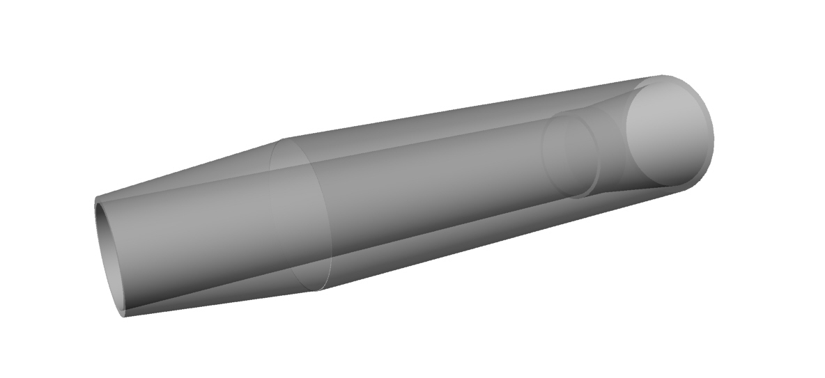
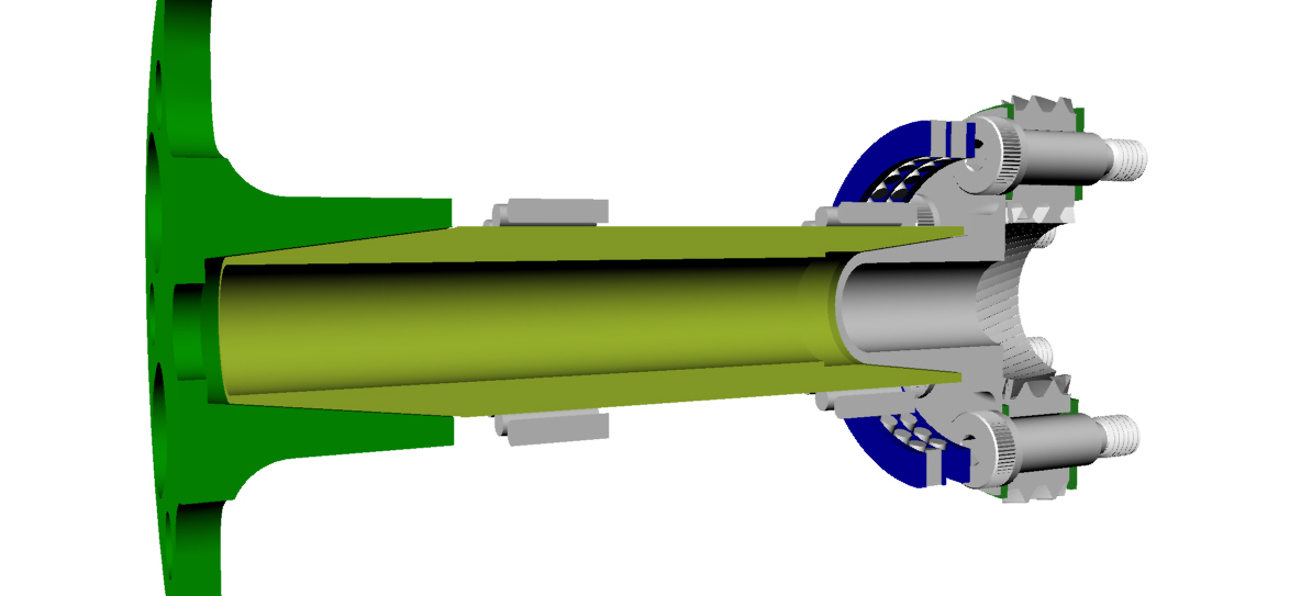
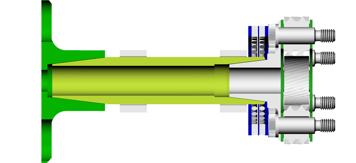
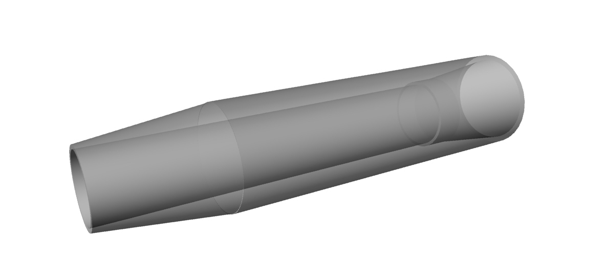
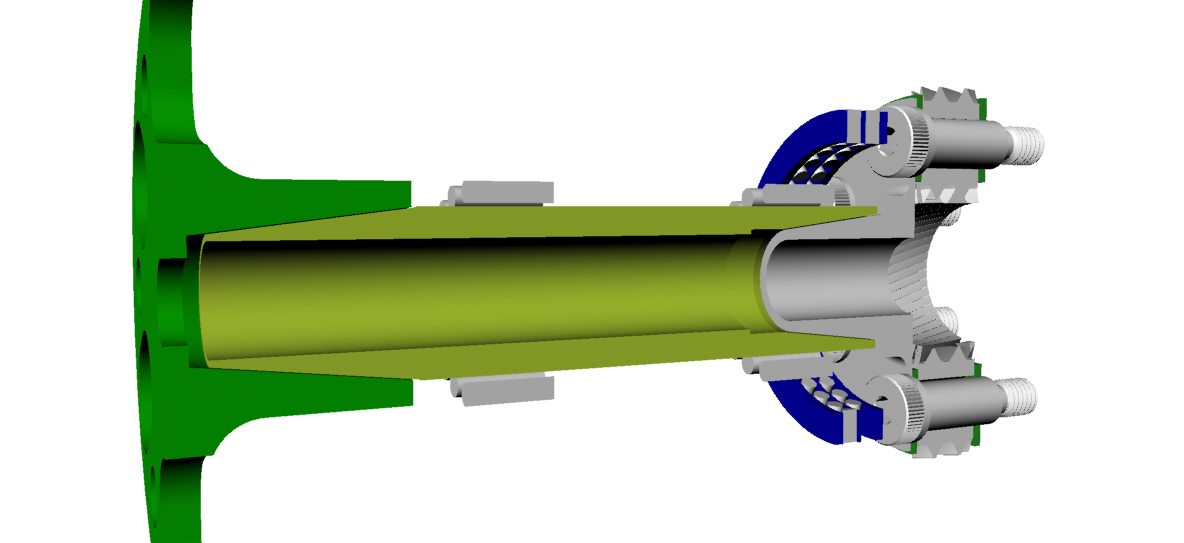
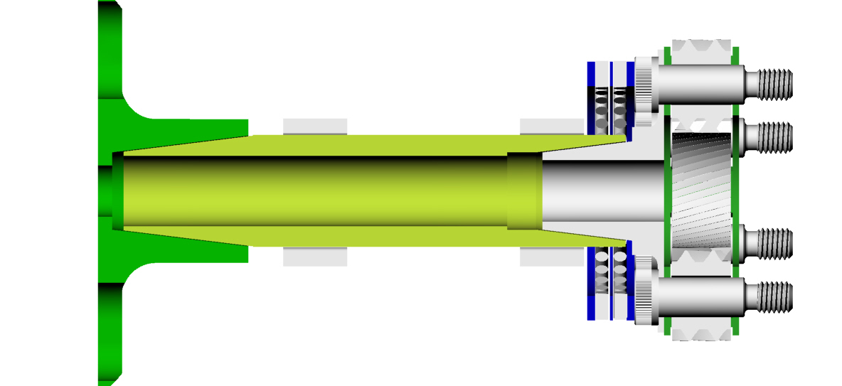
This is held together with a tension bolt. Not shown in the 3D.
This is the same way the three rotor is held together and the flywheel
is attached to the e-shaft on all rotaries.
No extended point set screws needed but could also be used.
No welding on the planet carrier flange like the Ross was done.
It is a seven degree taper which as I recall is a machine tool standard.
Uses roughly 2 inch diameter needle prop shaft bearings and thrust
bearings.
Paul Lamar
More pictures of the new taper prop shaft.
Still no tension bolt shown.
Paul Lamar.
I found this on the web and edited it somewhat.
A tapered shaft/hub is a common feature of shipboard machinery in the
Navy from on small pumps to 22" muff couplings in propeller shafts.
Usually these tapered fits are set by the designer establishing a "draw"
specification intended to result in a certain hoop stress in the hub.
Let's assume the permissible hoop stress is 35,000 PSI (Yield strength
for not heat treated medium carbon steel).
Say the taper is 0.05" in 2.25" that's about 0.282" per ft.
The draw would be (0.004" interference / taper per inch = 0.192") a hair
over 3/16"
OK 2" dia x yield / young's modulus = 0.002 ".
[Young modulus is 30 million for steel]
[yield for this steel is 35,000 PSI]
35,000 PSI x projected area of fit (2.25" x 2" x Pi) = 500,000 pounds
530,000 x 0.3 for coefficient of friction of steel Vs cast iron equals
about 148,000
pounds to break the friction.
My figures are quick and dirty maybe they should be checked.
Forest Addy
This is why you have to hit the flywheel with a sledge hammer
on a rotary after you remove the big nut.
The draw means how much the parts are forced together by the tension
bolt in inches.
A grade 8 half inch dia tension bolt can generate up to about 30,000
pounds.
A long 1/2 inch bolt is quite heavy and may not be strong enough.
This means this method will be heavier than the extended point set screw
method.
Paul Lamar
Here is another way of making a taper prop shaft.
Hog the whole thing out of 6 inch diameter solid
4140 steel with integral planet carrier flange.
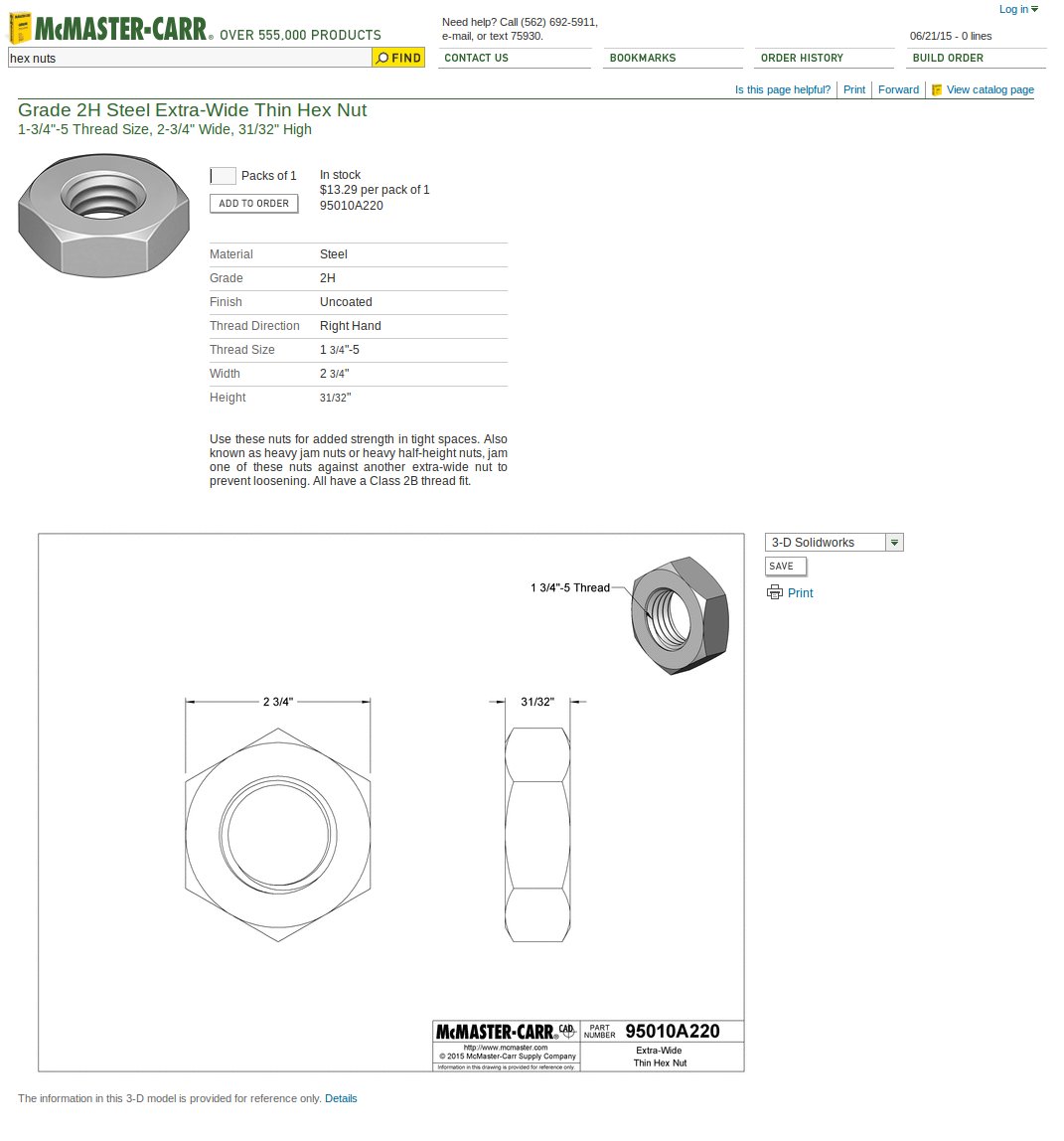
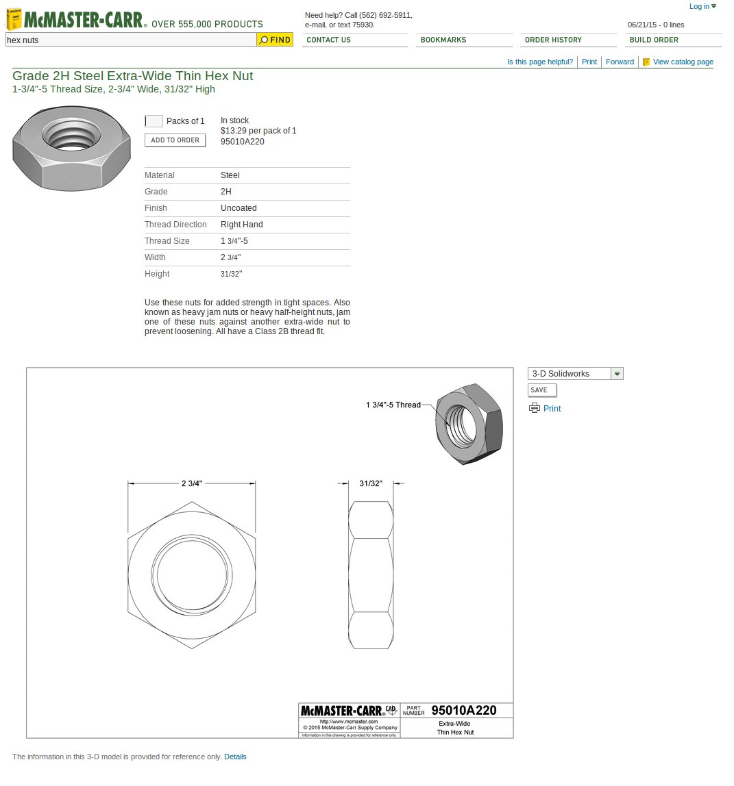
Use a large nut to hold the tapered prop flange
on as shown in the attachment.
This is lighter and stronger then a tensions bolt
but still not as light as extended point set screws.
Just like the 13B flywheel coupling.
No 3D yet but soon.
Paul Lamar
The Rotary Engine News Letter. Powered by Linux.
ACRE NL web site.
http://www.rotaryeng.net
You Tube
http://tinyurl.com/beqqxas
Store
http://www.rotarpower.com/#!
Copyright 1998-2015 All world wide rights reserved.