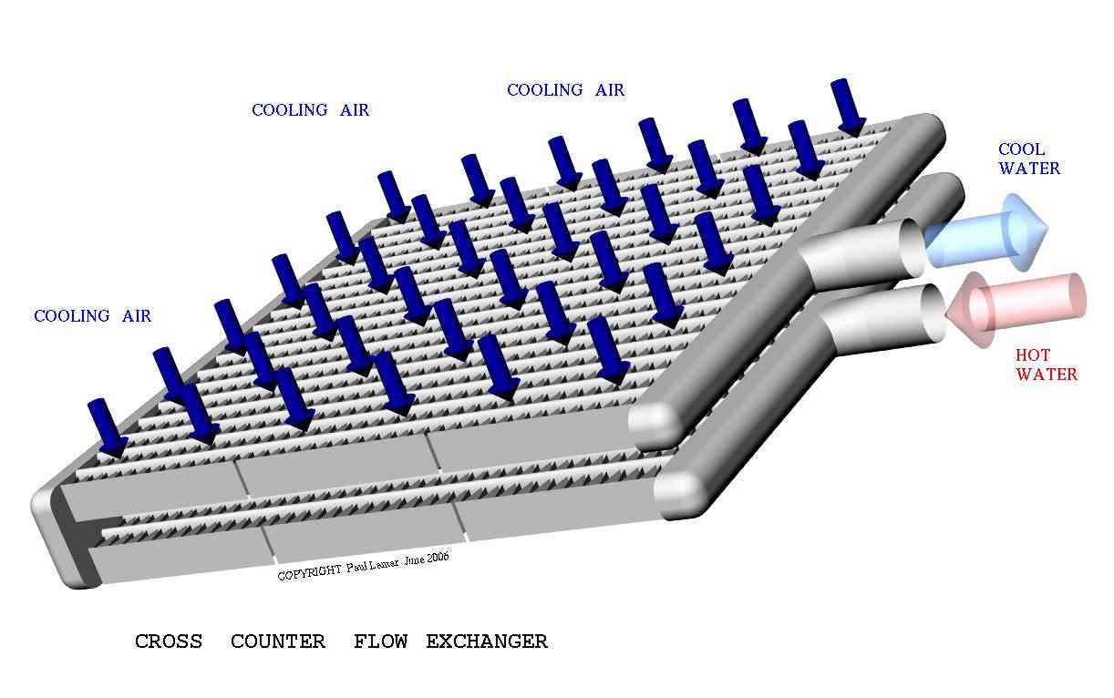
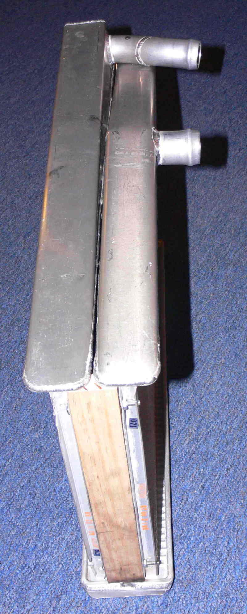
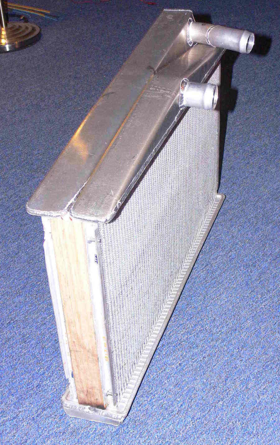
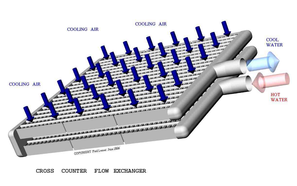
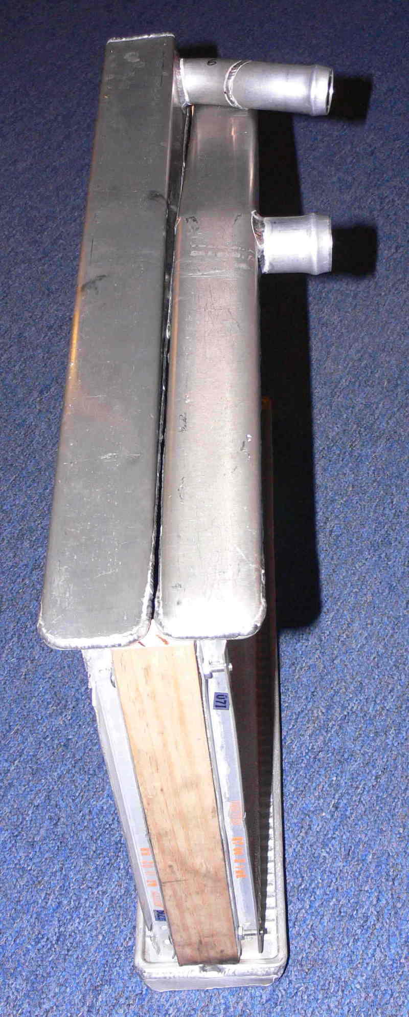
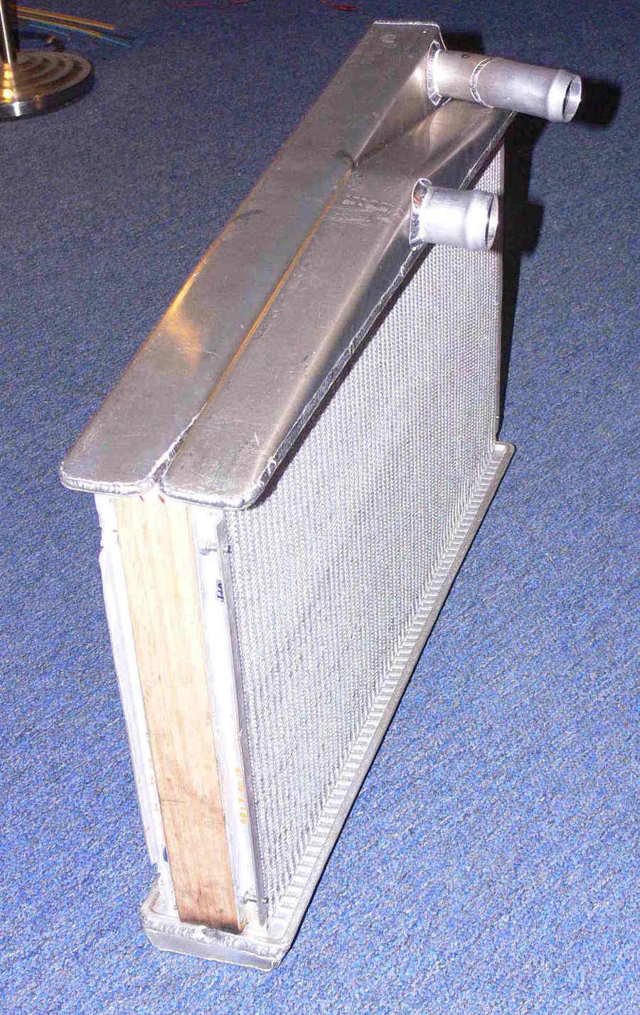
Cross counter flow is a more effective heat exchanger.
Here is the sequence for welding the rads to make a cross counter flow
heat exchangers.
Butt tig weld the in and out tanks first by cutting off all tabs on the
rads.
Don't weld the in and out tubes on yet.
They will be marked for position on the tanks while on the aircraft.
Then the large holes for the tubes will be cut and then the tubes
will be welded over the holes. The tank design will vary depending
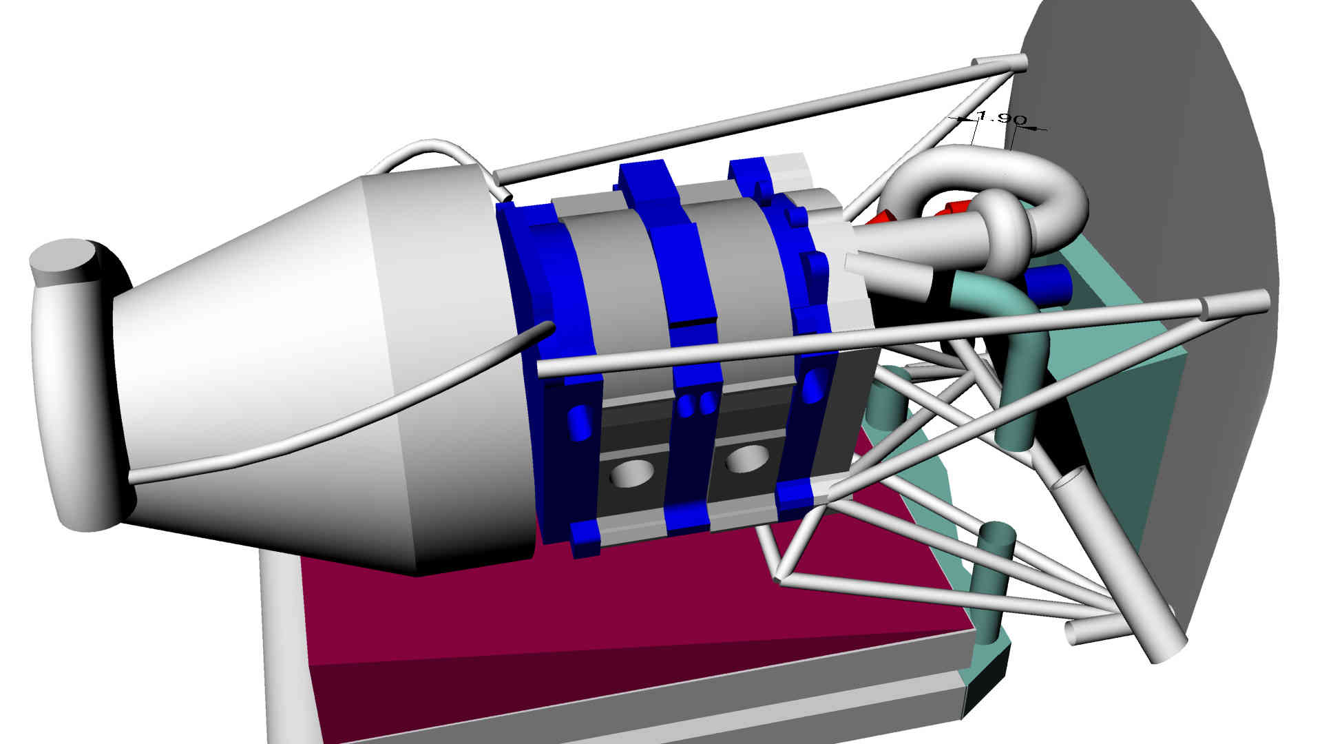
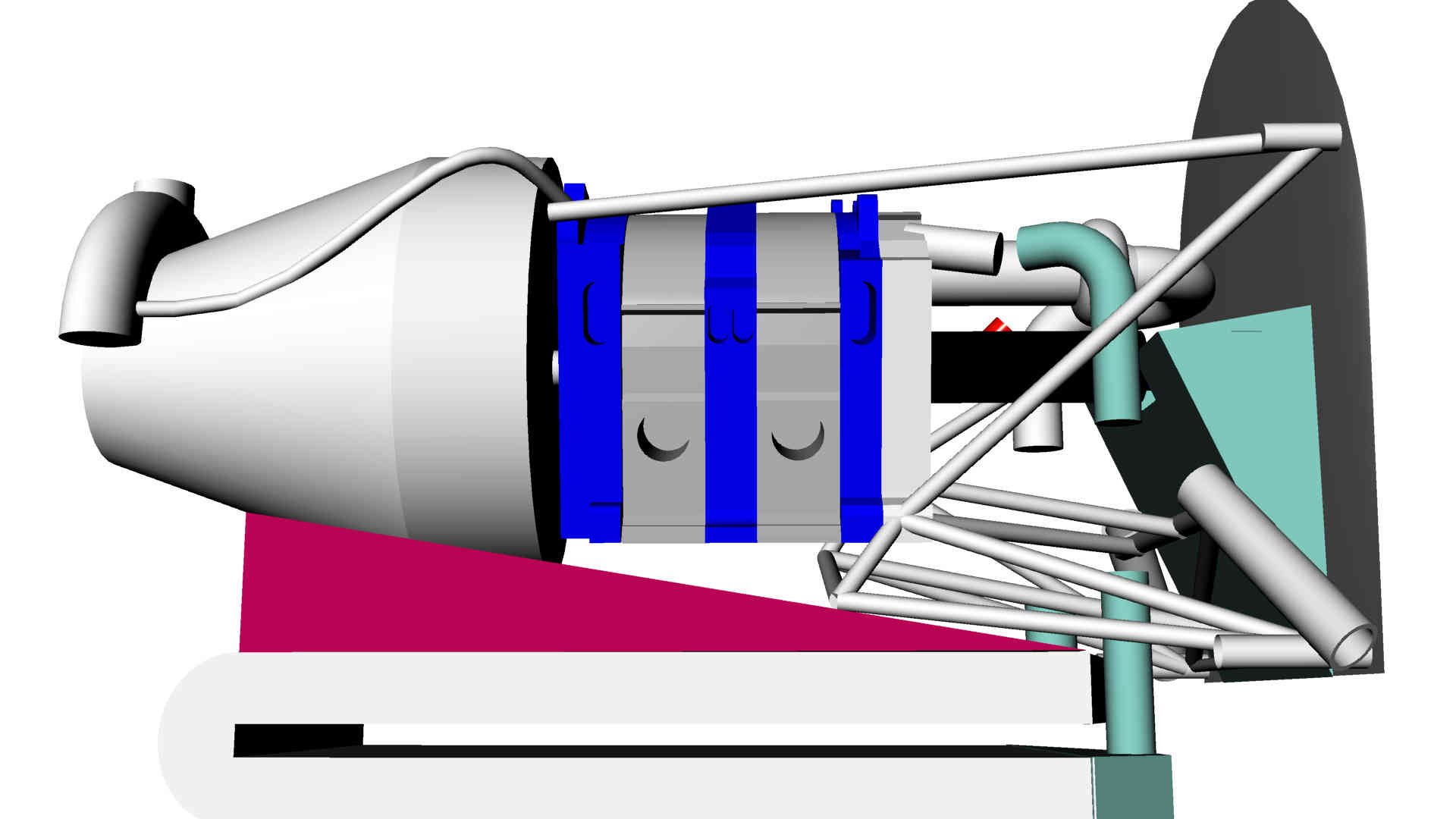
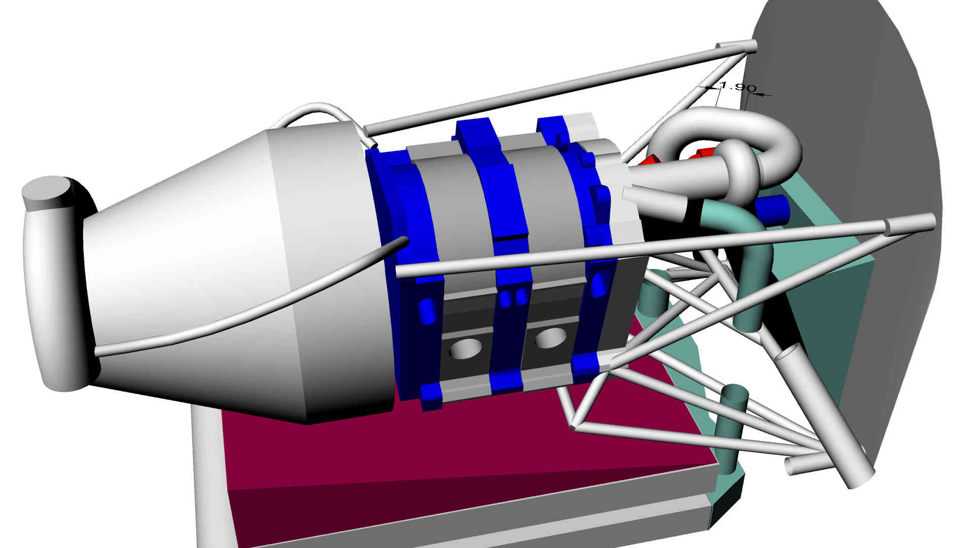
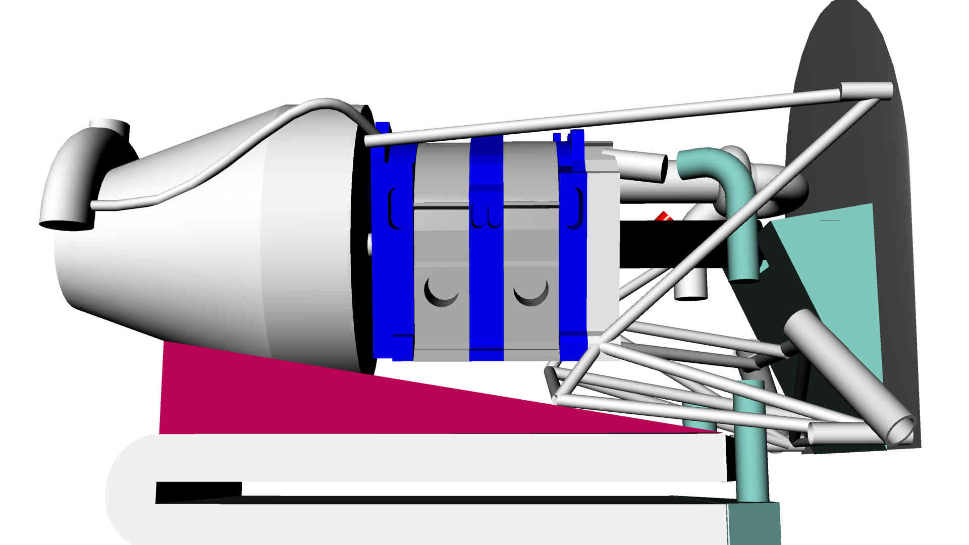
on cool side mounting or bottom mounting. The TTC is a bottom
mount. Most other aircraft use a cool side mount. The 3 rotor allows
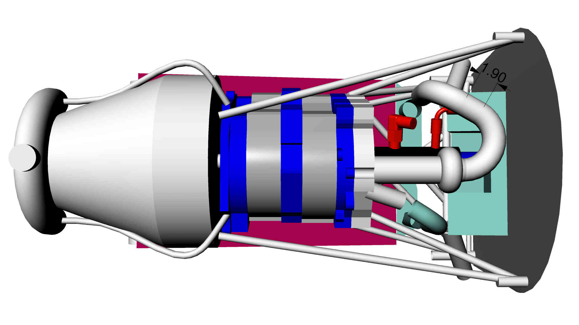
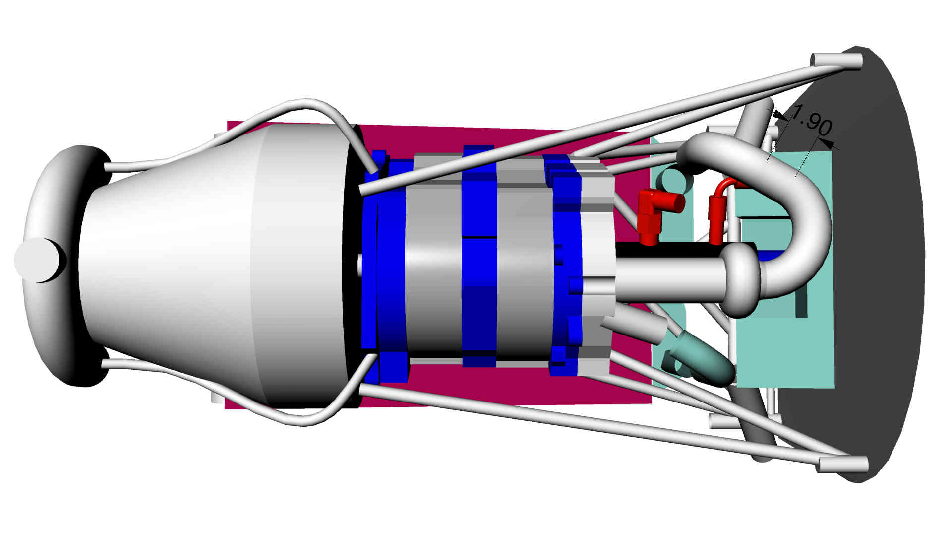
longer rads to be used. Put the diffuser between the rads and the
engine. See my book How to Cool your Wankel for more info.
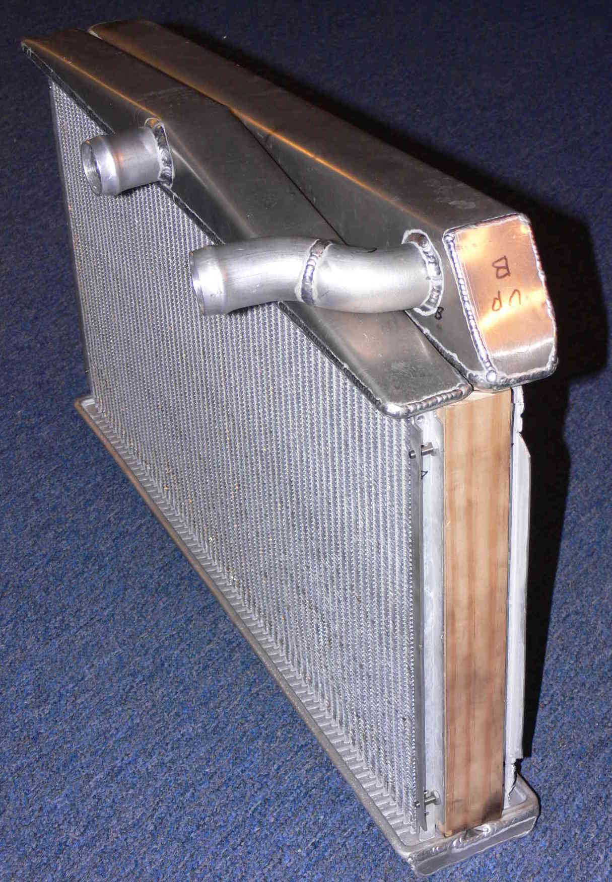
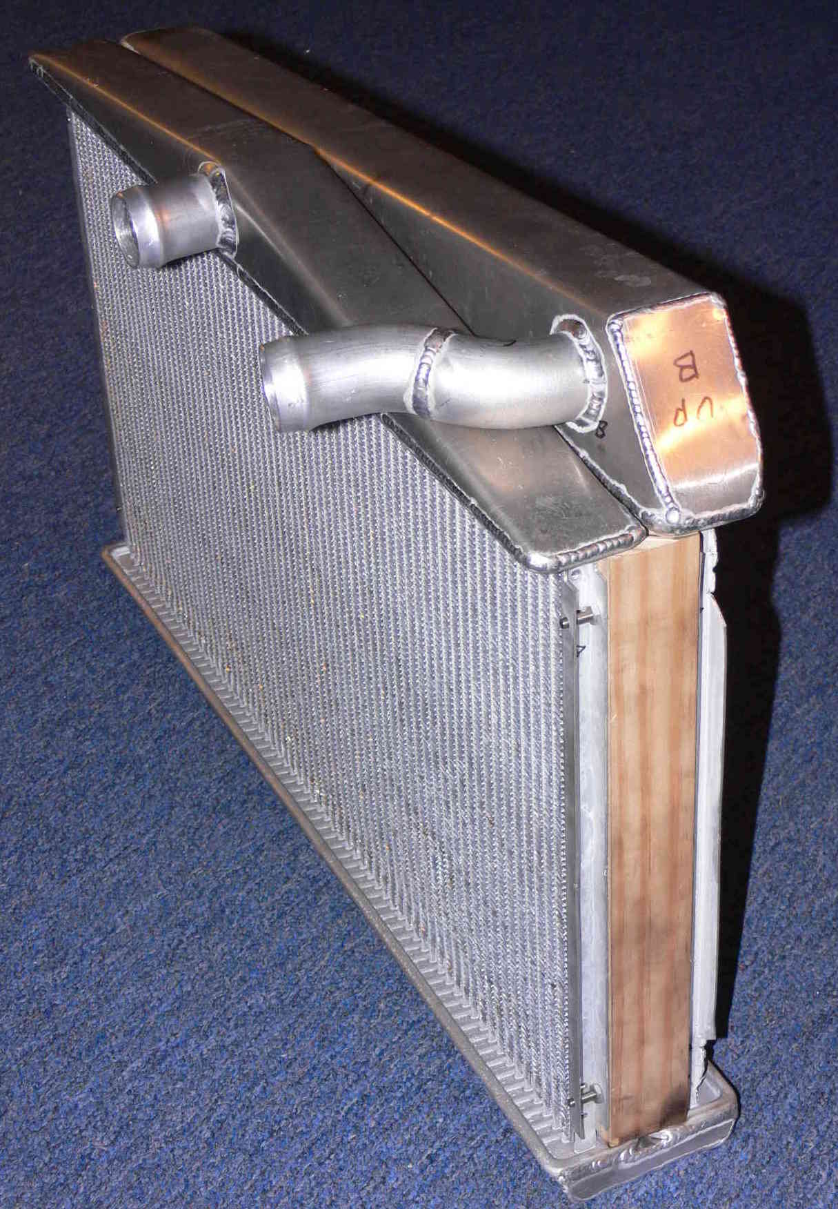
After the tanks are done (with out the holes and tubes) bolt the rads
together with the wood strips leaving 1/2 to 3/8 of an inch between
in and out tanks.
The idea here they must not touch each other.
The wood strips are heat insulators between the two rads.
Then weld an aluminium strip 1/2" to 3/8" wide at the other end.
Finish by boxing in the other end (the front end).
Weld on them some and let the rads cool some what. They
are brazed together at only 1100 F so it is important
to not get them too hot. Wet rags around the ends of the fins
and tubes might help.
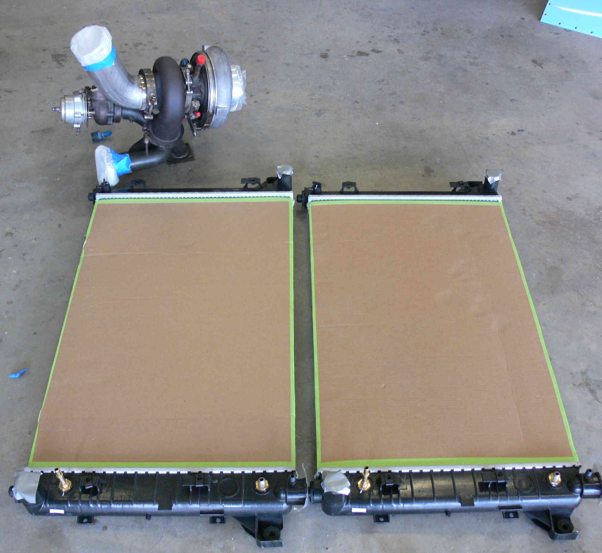
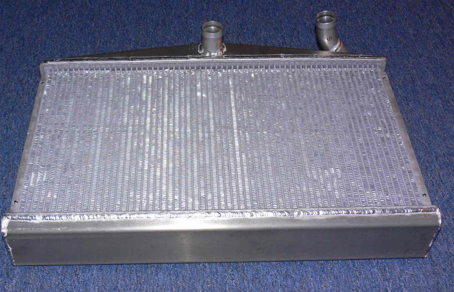
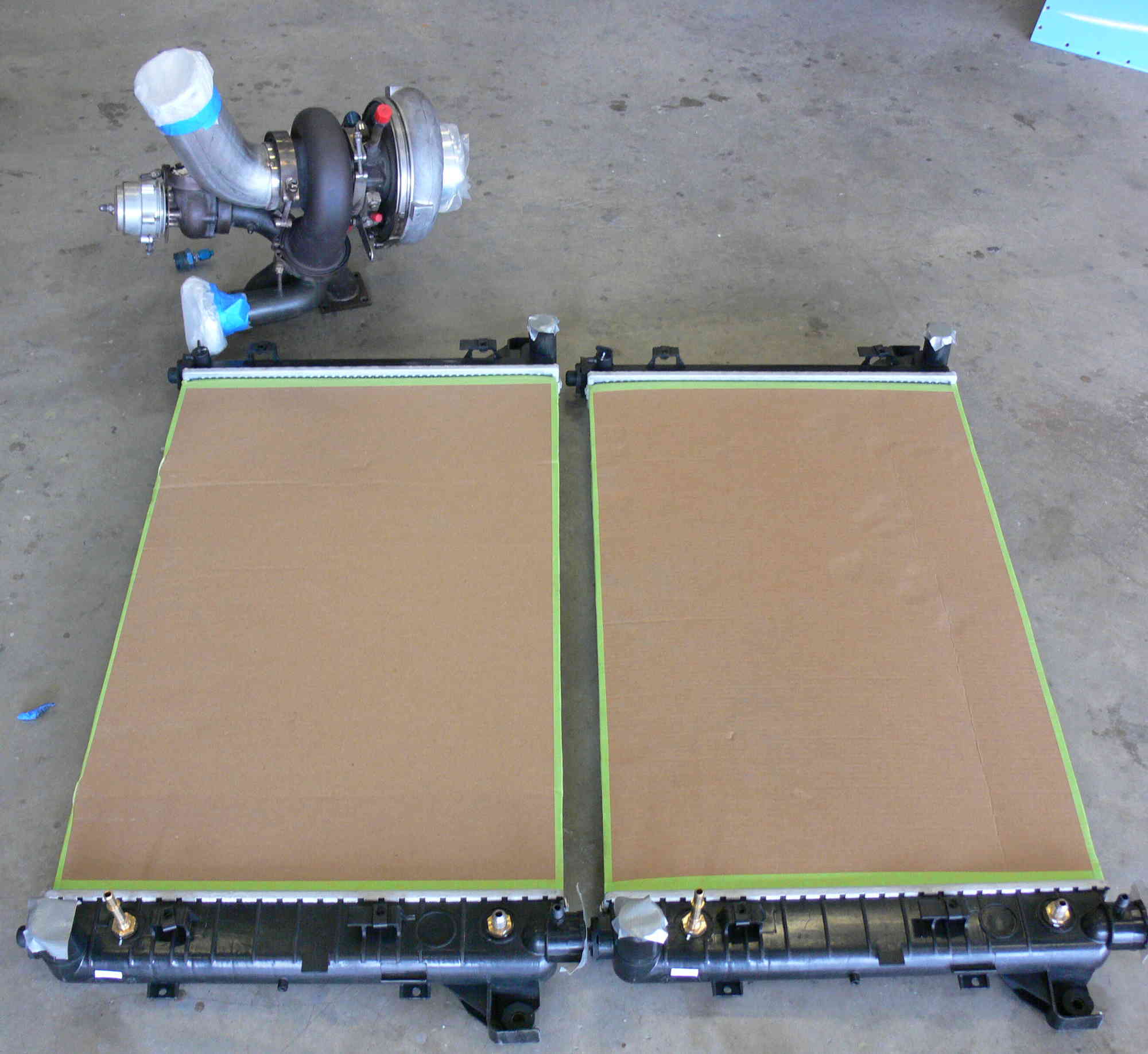
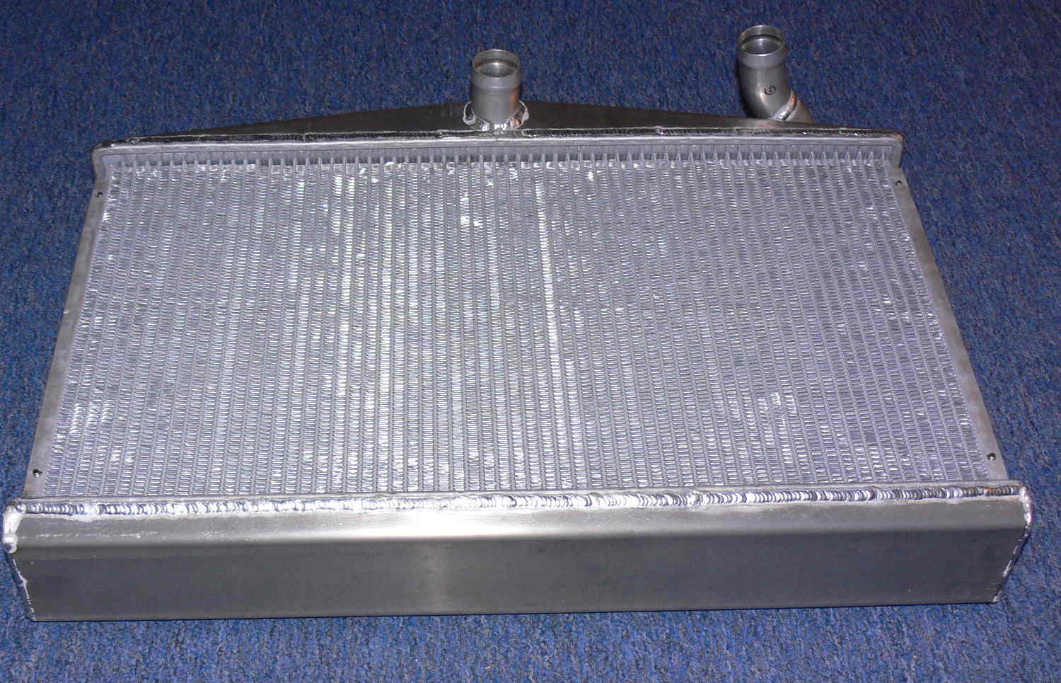
Here are a bunch of pictures attached. The JPGs were Dodge Neon rads
and not the truck rads. The TTC rads will be welded soon.
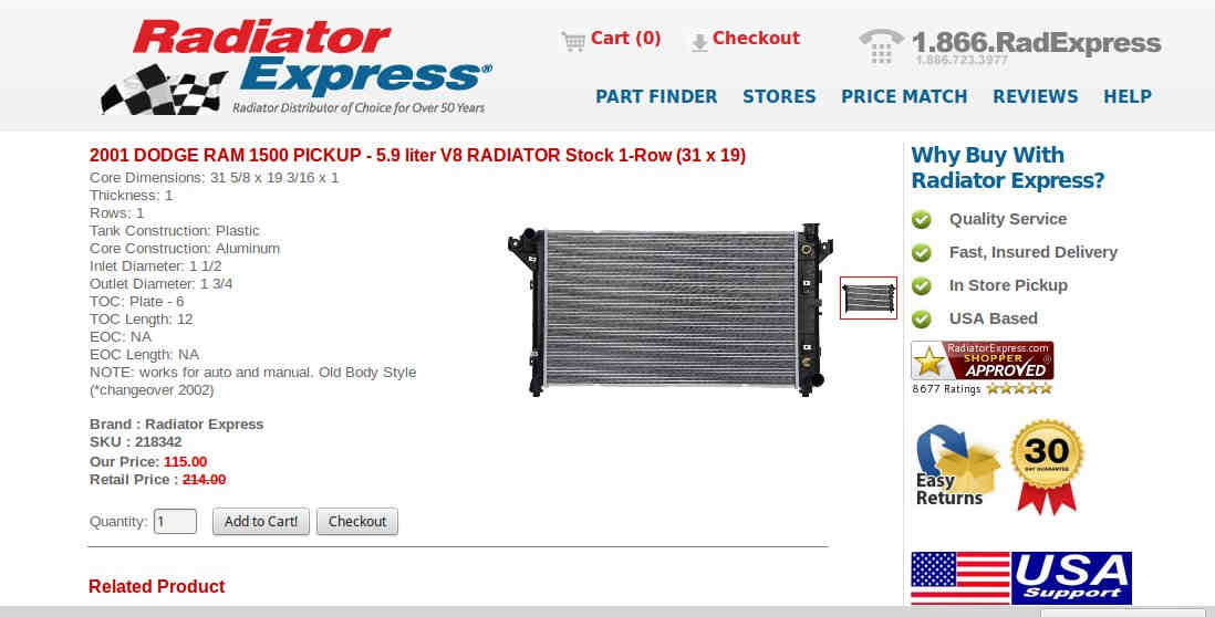
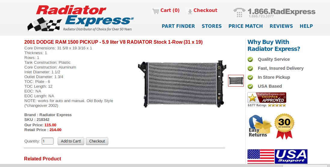
Apparently when Mercedes owned Chrysler they implemented some up
to date heat exchanger technology. IMHO Chrysler rads are now the best
from an
efficiency point of view I have found so far. Honda also uses up to date
tech
but they are more expensive.
Paul Lamar
The Rotary Engine News Letter. Powered by Linux.
If you want off the list PLEASE let me know and I will
remove you. ACRE NL web site.
http://www.rotaryeng.net
You Tube
http://tinyurl.com/beqqxas
Copyright 1998-2015 All world wide rights reserved.