I've been monitoring, with interest, your progress on silicone-rubber
torque damper design. Although I hope everything works out for you, I
wonder how well the silicone will hold up under long-term use. If I
remember my physics, the energy of the engine providing during the
peak torque will be stored within the rubber (somehow done by
stretching the polymer bonds within the molecular structure of the
rubber). This energy is then released when the torque is at minimum
value. On the following sketch, the quantity of energy
stored/released in represented by the areas on the graph; the area of
the peaks must equal the area of the valleys.
Just to keep the math easy, let's say that the area stored/released
by the rubber is 10% of the overall energy output of the the engine
(as represented by the compared areas on the graph).
A 200 HP engine puts out 150 KW of energy. This would demand that
the coupling would store/release about 15 KW of energy continuously.
Now we know that rubber compounds are not 100% efficient at storing
energy in their elastic bonds. The elasticity of rubber is measure a
number of ways. There are durometer numbers (related to hardness
and elastic-modulus) but it doesnt seem that these values relate
completely to the high-speed energy handling capabilities of
polymers. A number that seems to be more useful is the “coefficient
of restitution” used to compare golf-balls and such. Coefficient of
Restitution relates to the velocity response of deformed elastic
medium. It is interesting that a glass marble has a very high
coefficient, as do hardened steel ball bearings. Kids toy
“super-balls” have a high coefficient, as does the soft mushy
“silly-putty” that kids something play with. If memory serves, most
very-bouncy things still have only a coefficient of about 90% .
Bottom line is that it is possible that 10% of the energy
stored/released by the elastic- coupling will be retained as heat
withing the rubber compound … at that will be about 1.5 KW or 5000
BTUs of heat.
I think it is likely that you could have a heat buildup problem
resulting in rapid coupling degradation
RBerglund
Silicon is good to 500 F and there is a lot of aluminium to carry
away the heat and dissipate by the rotating coupling.
I am not worried.
Paul Lamar
It's all theory until the flight test is done. Then we will know if
these couplings are a pipe dream or bullet proof. I'm looking
forward to the results.
Mark LaPierre
Interesting conversation! Perhaps the heat capacity and thermal
conductivity of the silicone should be considered, and that of the
housing itself. That would tell us how a material's temperature
changes when it absorbs energy, as well as how those materials would
be able to conduct away the heat generated from the compression and
release of the elastomeric material. We might be able to work out
what a steady-state temperature might be for a given energy input.
Not that I am doubting Paul. But it seems to be a question on
peoples’ minds. Actually, it was on MY mind too! I was wondering
how one might size the coupler safely. Might be fun to actually
generate some numbers. I will look into it.
Gene Kahn
The time to climb coupling will be the acid test as it is roughly 3
times the HP and only 15% larger. We have room on the engine part
for radial cooling fins if necessary..
Paul Lamar
As regarding how a material changes temperature as it absorbs
energy: In the early 1970's, I worked as a corner marshal at the
Edmonton International Speedway. During a Trans Am race one of the
cars lost its driveshaft about 1/3 of the way up the 3/4 mile main
straight. As it came to rest almost in the middle of the track we had
to remove it. One of the other workers went to retrieve it while I
flagged and safety watched. He tried picking it up but quickly
dropped it as he burned his hand. You must know that it was not
radiated heat from the exhaust as two 4 inch pipes does not fit in
the tunnel with the driveshaft. Hot air from under the car and
conducted through from the transmission maybe but just the flex from
the torque during acceleration and deceleration puts a lot of heat
into the driveshaft.
Dale Davies
These are the types of couplings used on some car drive shafts. The
bolts are cantilever out of the transmission shaft flange. They
fatigue and fail due to repeated bending. Built in cracks at the
root of the threads. The manufacturer warns against this scenario.
I think this is the one that failed causing the aircraft to crash.
Paul Lamar
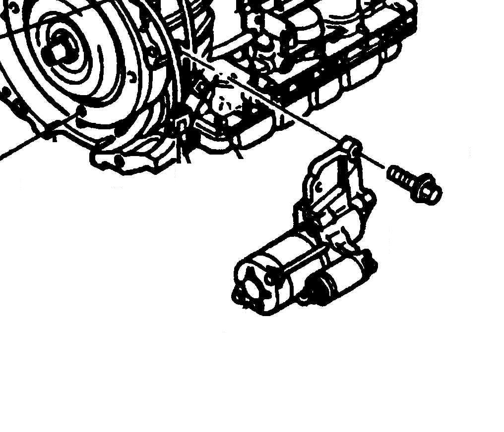
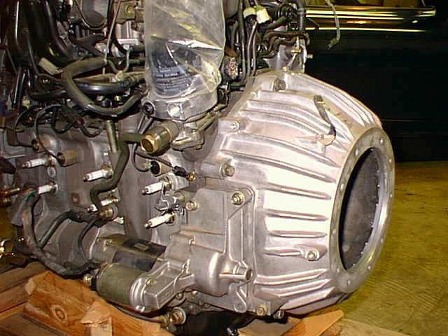
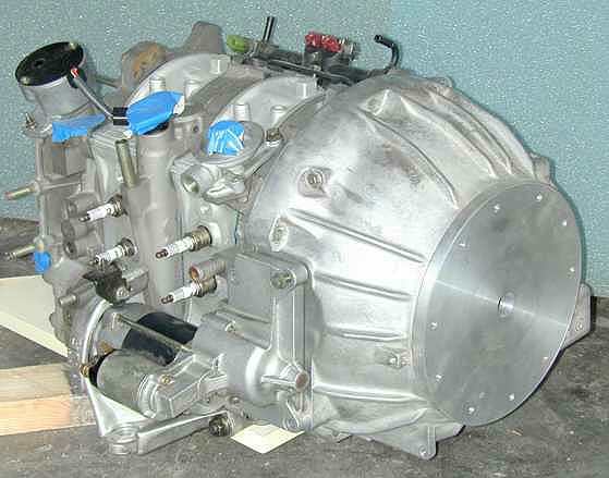
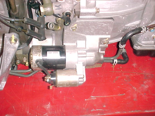
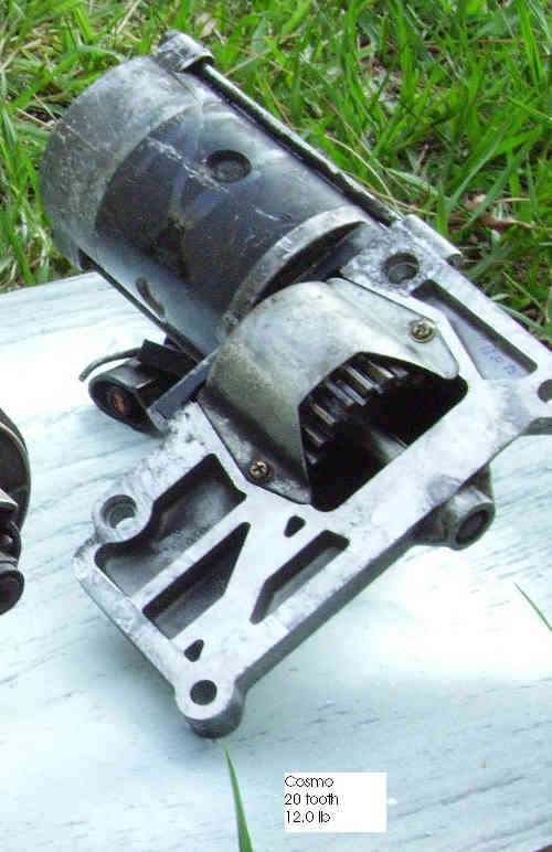
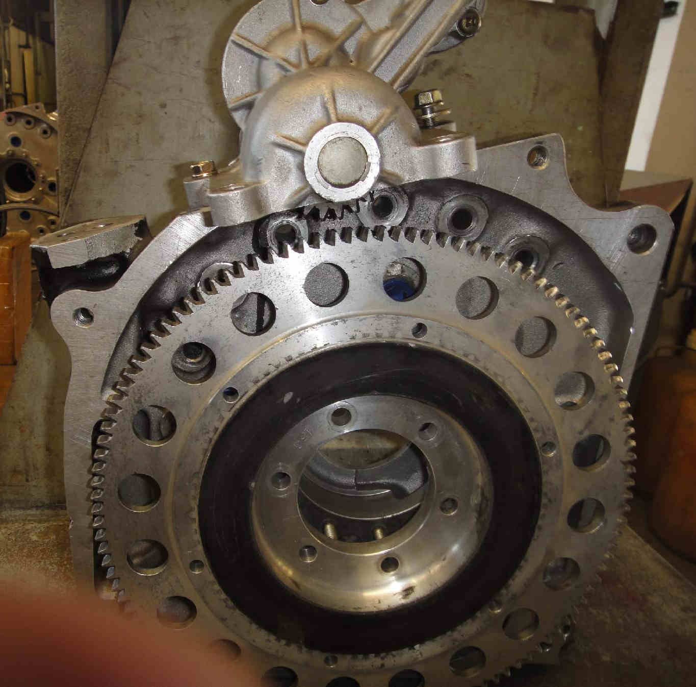
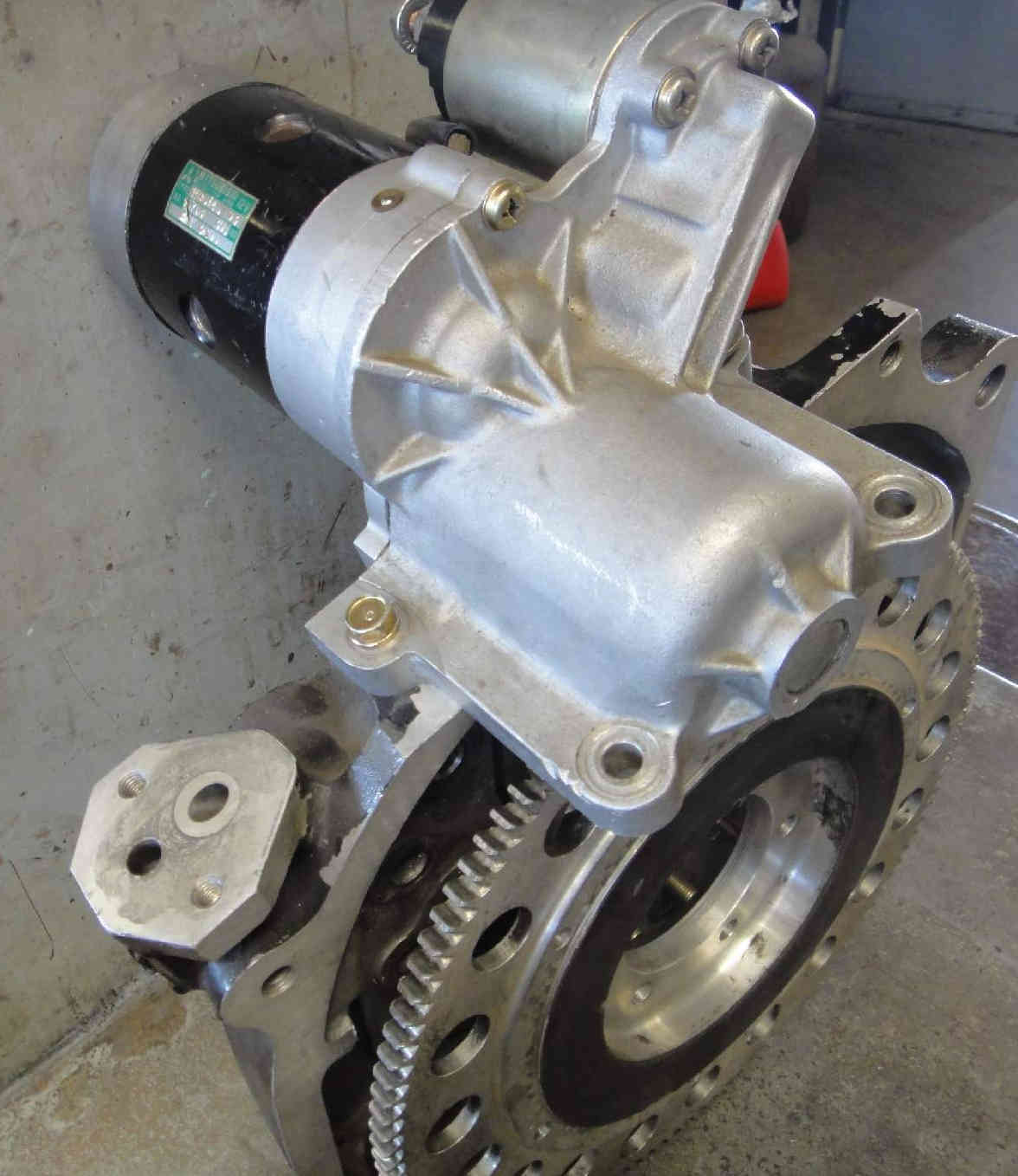
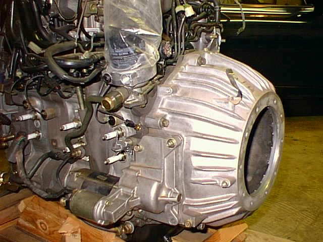
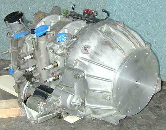
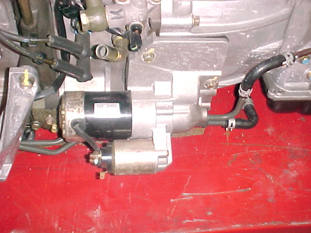
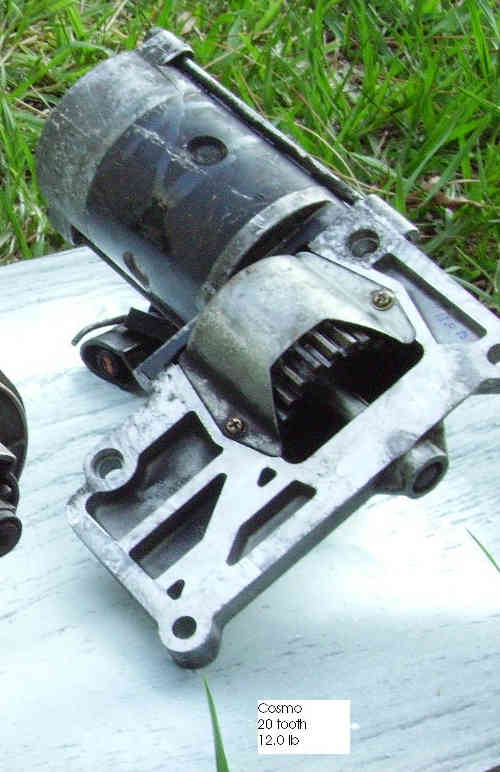
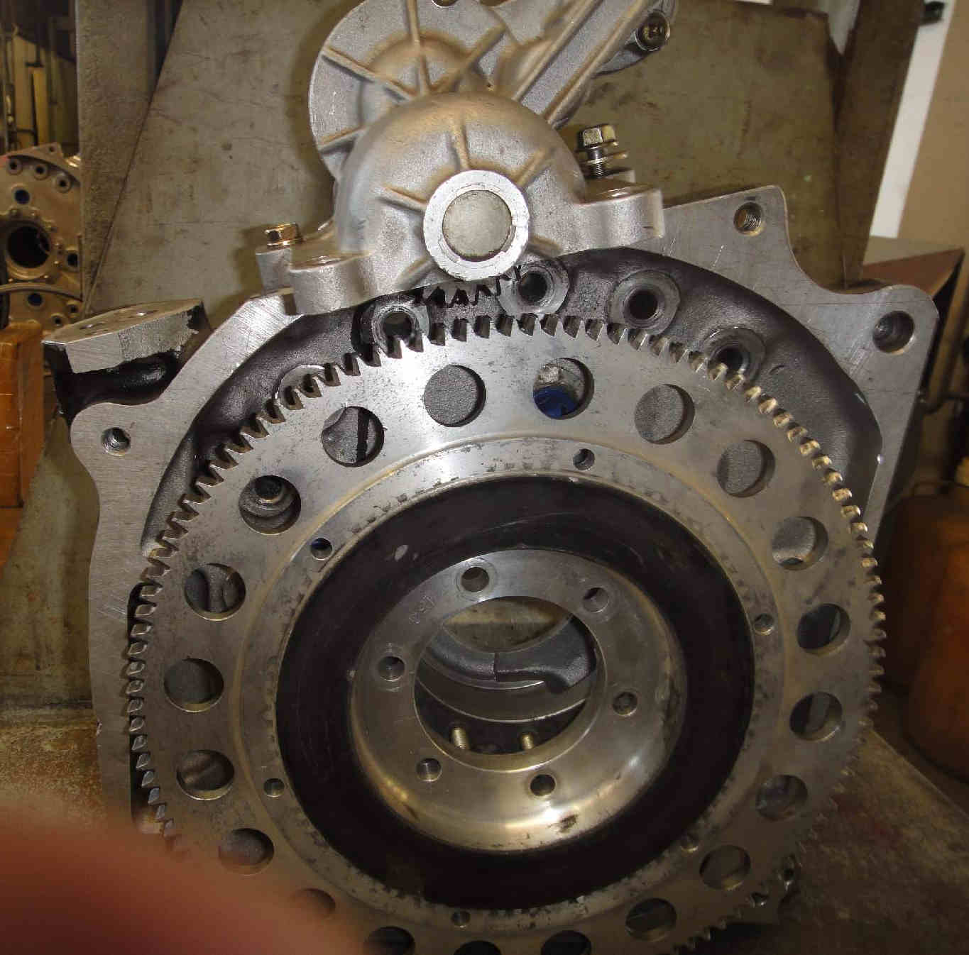
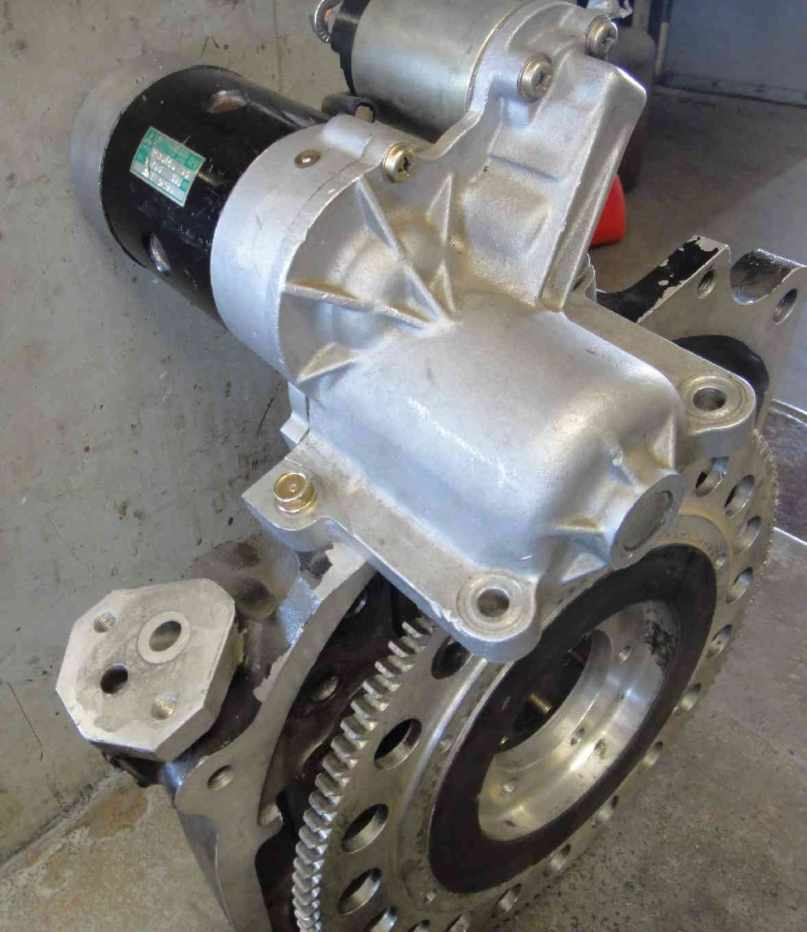
I'm assuming that larger pinion up against the ring gear is attached to
the starter. Where can we get that setup?! Adaptor plate to fit that
between rear iron and bell housing? I bet that cures any flooding hard &
starting issues. Spinning the engine up a lot faster than factory setup!
Dan Gorsine
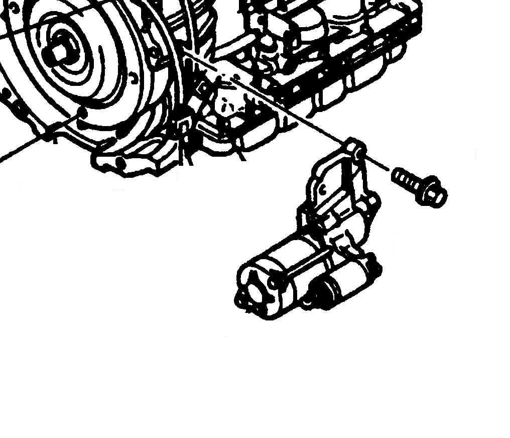
Good question. I don't know. It does not look like a Mazda
3rd gen auto tx or RX8 auto tx starter.
Most likely an auto tx starter from a larger engine. Maybe Chevy or Ford.
Paul Lamar
The Rotary Engine News Letter. Powered by Linux. If you want off the
list PLEASE let me know and I will remove you. ACRE NL web site.
http://www.rotaryeng.net You Tube
http://tinyurl.com/beqqxas
Copyright 1998-2015 All world wide rights reserved