How do I get up to speed on selecting and connecting up a
turbocharger for my airplane?
Gary Schwarz
The bible on this subject is Turbochargers by Hugh MacInnes.
See the attached files. There are a couple of others that I listed
that are not bad.
By far the best web site.
https://turbobygarrett.com/turbobygarrett/turbo_tech_basic
The stock Mazda Turbo II manifold cracks. The second version is
better than the first and can be welded up and modified. radius all
sharp edges to at least 1/4 inch. Mazda failed to do that.
Top of the line is an Inconel manifold.
If not that make it out of .125 thick 321 SS tubing or plate.
Paul Lamar
Beautiful welding.
milo
A Maximite data acq system would be invaluable for a turbo
installation. The bottom line is how much boost do you get for x
amount of exhaust back pressure over a range of RPM's. That is
related to fuel burn. The Maximite will record at high speed up to
ten parameters.
One book I was disappointed in was Turbocharging Performance Handbook
by Jeff Hartman. Mostly just pretty pictures.
Paul Lamar
Gary:
I am working on a turbocharged RX-8 also--mostly due to the
complication of TIG welding up 6 x 20" intake tubes draped over the
top of the engine (bellmouthed into a plenum) for the naturally
aspirated intake-- and also the noise factor which would require at
least a 10 lb muffler.
It appears installing a turbo might be a wash in terms of labor to
weld intake and exhaust-and the overall weight (muffler possibly not
required for turbo version).
It appears an intercooler is a very good idea (if not required) as
the RX-8 has about a 10-1 compression ratio.
I am essentially looking to turbo normalize the RX-8 to get about
200-250 HP at any altitude < 18000' at 6000 rpm cruise and 7700 rpm
take-off (with Tracey's 2.85-1 reduction drive).
So far I have reduced the choices to:
T04E-50 trim, F1-62 turbine, A/R = 0.68 (possibly bigger). T4-4-bolt
flange, 3" dia. V-band outlet. 3" dia. compressor inlet & 2" dia.
outlet. External wastegate. See turbonetics catalog for details.
This is partly based on one flying in a Cozy IV with good results.
Let me know what you discover.
Regards,
Richard Craig
I don't recommend the six tubes over the top. It is much easier to
take the engine apart and p-port it. Just spend some time to make a
compartmented container to store all the seals so they go back in
exactly where they came out of.
The engine is a lot easier to take apart and put back together than
it looks. Don't be afraid of doing that. If you wish buy a old 12A
or 13B and use it for practice. Download shop manuals from here.
http://foxed.ca/index.php?page=rx7manual
Plan B is wait awhile until we get a handle on the Helmholtz
resonator. If that works you can just cut off a stock RX8 intake
manifold and weld on a rectangular tube.
A turbo is a good idea as it gives a lot of power and 10,000 feet
for high speed cruise. It also replaces the muffler.
http://www.turblown.net/store/index.php?categoryID=22
Paul Lamar
I would recommend an A/R of closer to 1, maybe a bit higher. A low
A/R is useful to limit turbo lag in cars because it uses a smaller
turbine wheel and tighter case. This lets the turbine spin up fast
and turn faster resulting in less wait for the power surge. The first
drawback for aircraft use is that the smaller wheel gets a more
concentrated heat load. Couple that with its higher speed and you get
premature failure. The second is that since the turbine turns several
times faster than the higher A/R units, the shaft wear becomes an
issue. For mine, I have a T04 with an A/R of 1.06. It has a larger
slower turning turbine and a larger surface area for heat
dissipation. I am also placing it 18" downstream to allow the exhaust
to cool before it reaches the turbine. I work on aircraft, and my
latest is a turbo Seneca II. Her turbos are 1.06 A/R and have a TIT
limit of 1500 degrees. My rotary exhaust comes out single 2" tubes to
a 2.5 then t a 3" before it enters the turbine. I also have a cooling
shroud similar to normal aircraft heater cuffs around the exhaust to
help cool the exhaust. This shroud coupled with the expansion of the
gasses should keep the TIT under control and keep my turbo from
failing.
So far the turbo failure mode for the rotary engines in aircraft has
been primarily due to heat. The stock turbo fails because the turbine
gets hot and centrifugal force stretches the metal to the point of
contact with the housing and failure. And, these turbos were meant
for stoplight to stoplight racing, not 8 hours of continuous use with
1800 degree exhaust. My solution includes a turbine that will turn
slower, dissipate more heat and with the exhaust cooled should
function well. It should be noted that in every certified aircraft
that I have worked on that has a turbo, they are located way
downstream of the exhaust ports in the engine. The Seneca II (Connie
6 cyl IO 360) has all 6 cyls exhaust come into 1, it goes from 1.5 to
2" for about 6 inches, then into the turbine. My EGTs when leaned run
about 1350, my TIT runs closer to 1200. Cooler temps = happy engine.
Even the Cessna TTX which has 2 turbos, one on each side of an IO 550
has the turbos located almost at the firewall as far from the exhaust
ports as they could get it.
As far as an intercooler, I would say definitely yes. Compressed air
from a turbo can reach 400 degrees plus. However, if you used a carb
like the old Chevys and some drag cars and place it upstream of the
turbo the evaporation of the fuel will cool it somewhat. The downside
is that you have a compressed fuel air mixture that in the event an
intake hose comes loose or leaks would become a very effective blow
torch. Not recommended.
In Summary-
Larger preferably ball bearing turbo. Could also use a marine turbo,
these have water jackets for cooling and use the engine cooling water
to keep the turbo cool. You would need a bigger radiator.
A/R of 1 or better, particularly on the turbine side. Mine has a .96
on the compressor side.
Mount the turbo behind the engine, put as much room for cooling
between the engine and the turbo as you can.
Enlarge the exhaust to encourage expansion as this will cool the
exhaust.
Shroud the exhaust and feed it with SCAT tubing forced air that
dumps overboard.
Oil- the aircraft turbos feed oil from the BOTTOM and it is returned
to the TOP of the engine in the accessory case so that at no time can
the turbo not be FULL of oil. No gravity return and drip like cars
do. Comes in at 3/16 leaves in 1/4. This arrangement also lends
itself to the installation of a small oil cooler to cool the oil
before it dumps back into the sump.
Kevin Alderman A&P, GROL, CFI (the last ones are new letters ☺ )
Well put. You amaze me Kevin :)
Paul Lamar
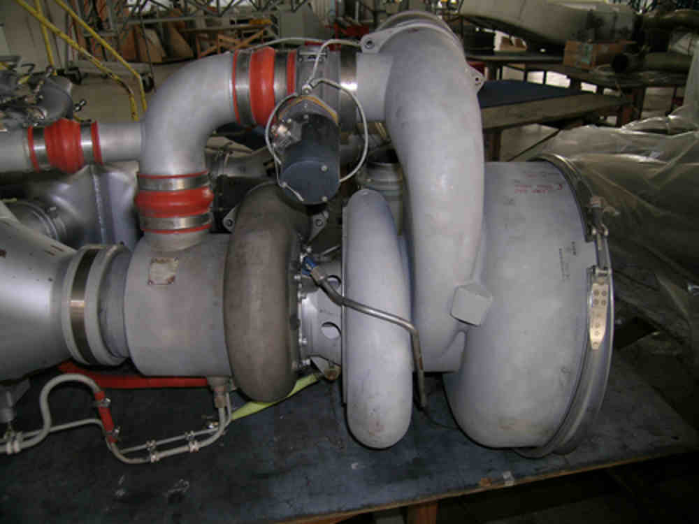
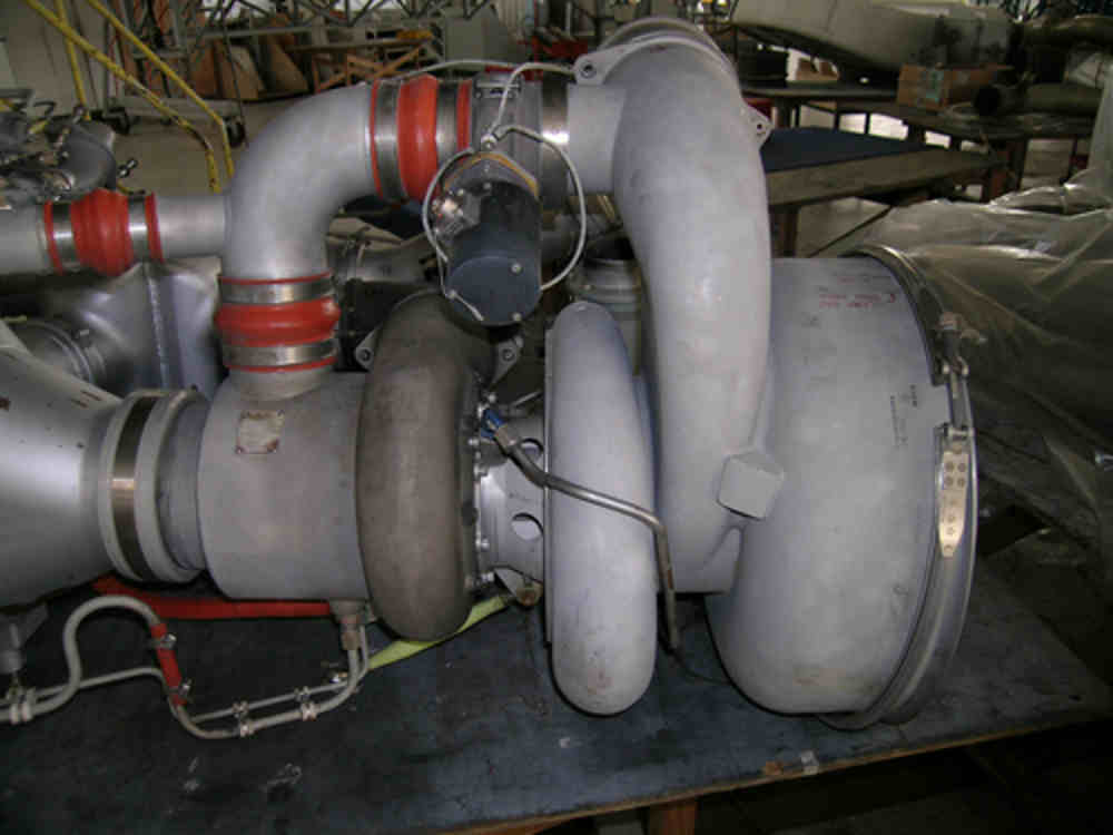
Here is a pic of a jet air conditioning system. It is just a series of
turbines. The hot air comes off of the compressor section of the engine at
around 400 or so degrees. Some of this air is used to pressurize and heat
the cabin at altitude, some is used for heating the leading edges of the
wings and intakes of the engines for deicing.
At lower latitudes and hotter
climates the Air Conditioning- i.e. cold air is provided by running this
hot air through a series of turbines that go from small to large. With each
trip through the turbines the air loses energy to the turbine, and then the
air is expanded i.e. decompressed- to cool it further. The result is cooler
drier cabin air without the weight and complexity of using a refrigerant
based evaporative cooling system.
If you look closely below, you can see that this behemoth uses multiple
compressor and turbine sections connected on a common shaft. The air just
hops from one to the other. If the mass of the air is constant, you can see
that the volume of the chambers increases so that the air pressure can drop
which will result in the release of the heat energy (cooling) and an
increase in volume. As the volume expands the amount of energy is
dissipated and the air is cooled.
What I described earlier is based on this concept.
[image: Inline image 2]
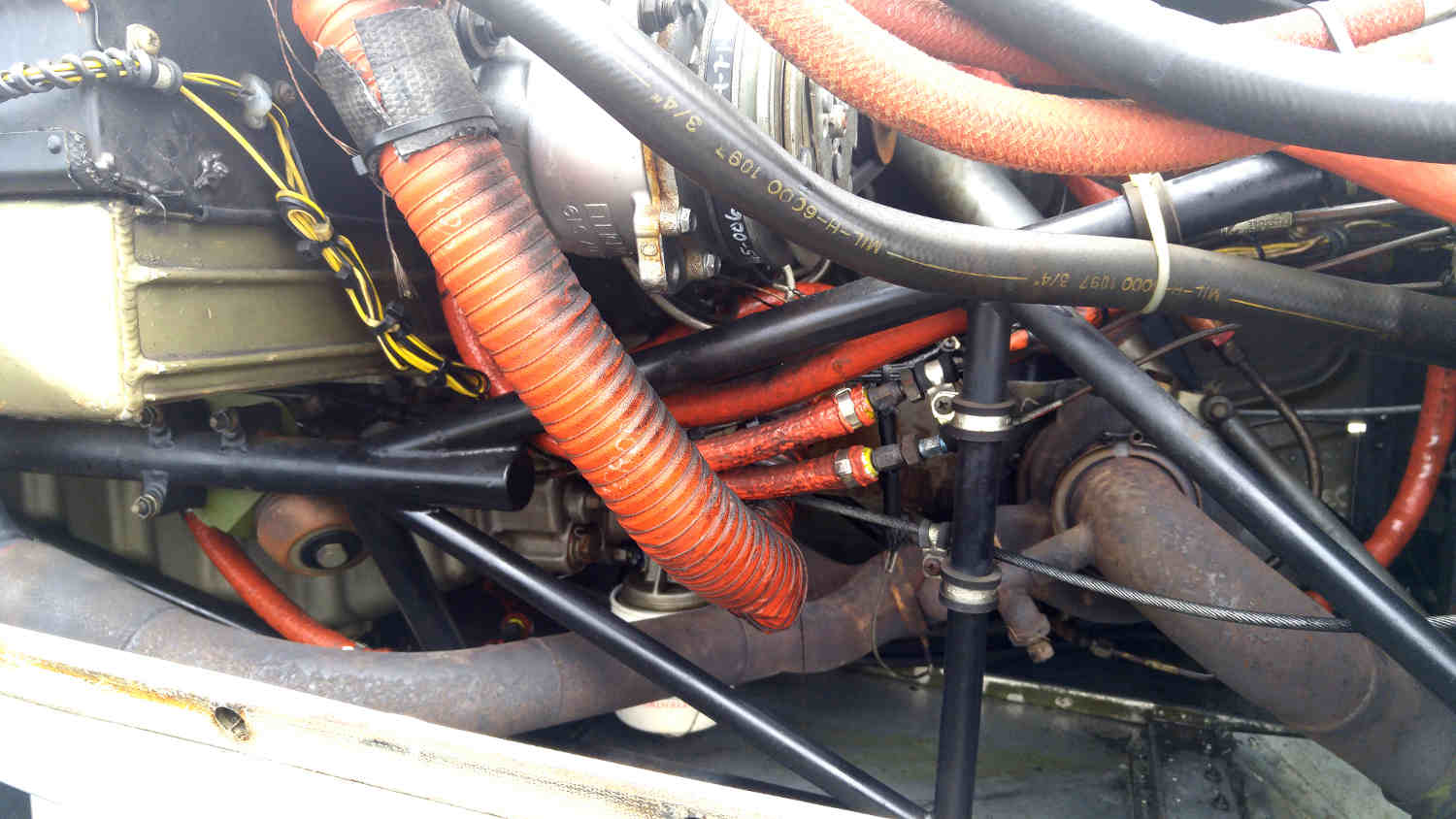
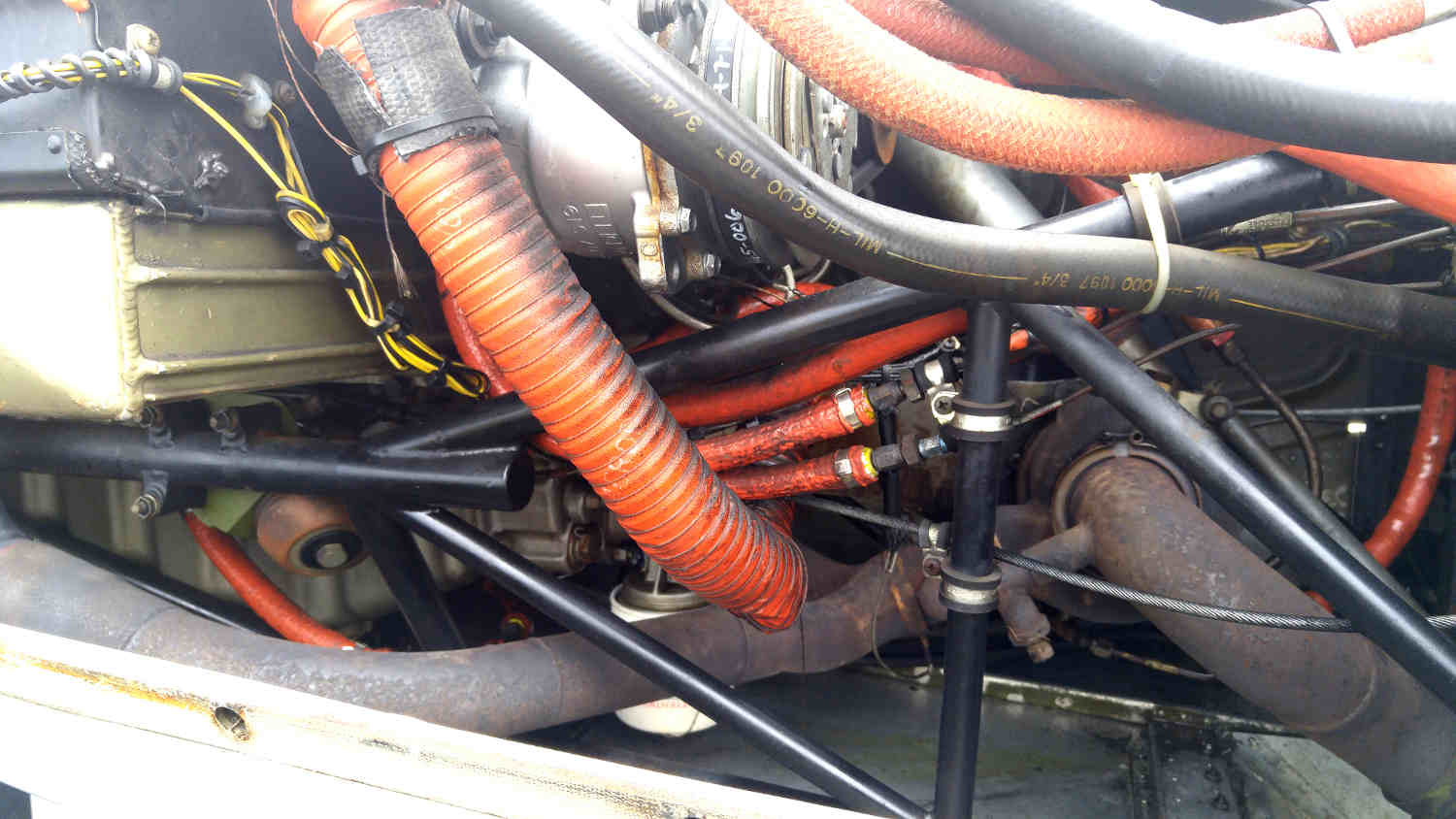
Here is a pic of the Seneca II with its Continental TSIO 360 turbo. Notice
that is is way behind the engine, long exhaust tubing and if you look hard
at the top right of the turbo in the pic you can see the oil line that goes
up to the accessory case. This is how we get 1200 degree TIT and 1350
degree EGT. Now look at the lower front of the turbo where the exhaust
tubing comes together. It grows from the single 1.5" up to finally a 3"
with a 3" exhaust.
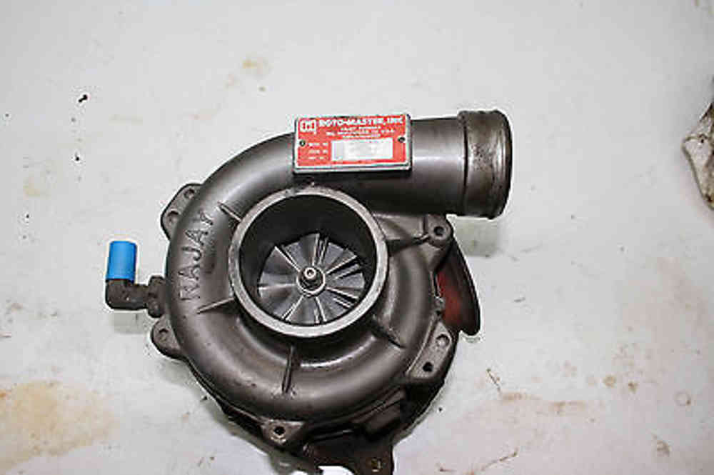
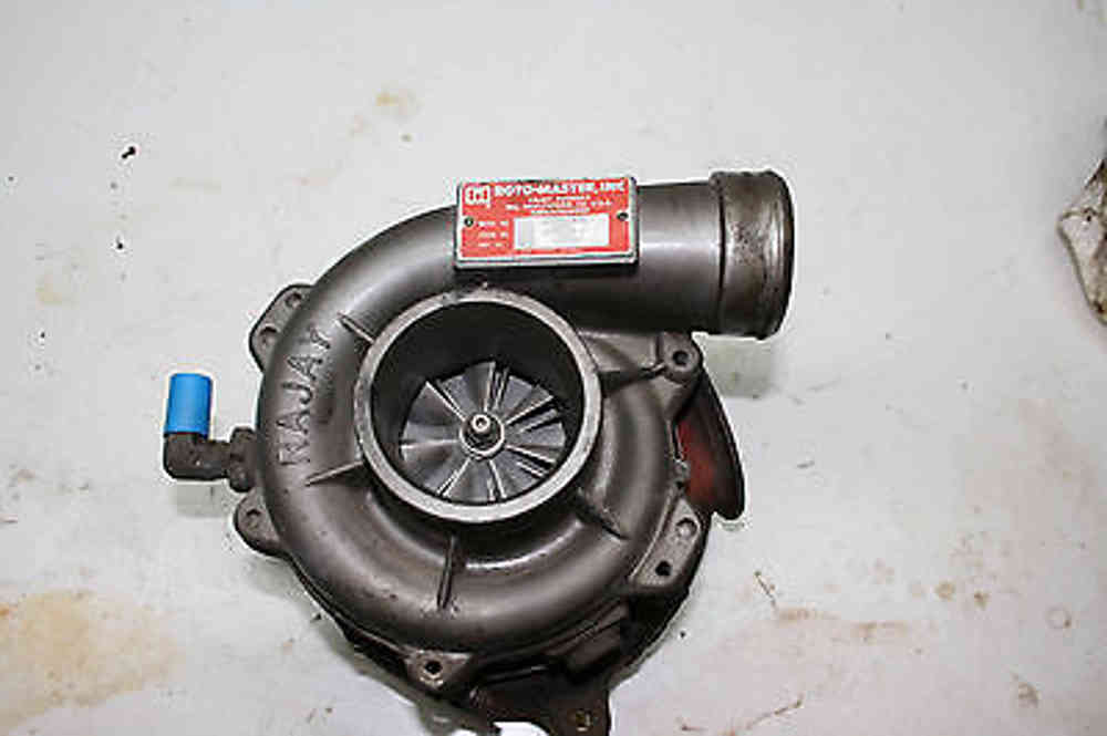
This turbo is a RaJay stamped with A/R of 1.1
[image: Inline image 4]
Notice how big the turbine and compressor housings are. That is a result of
the desired high A/R ratio. The Seneca that I fly maxes out the boost at
38" with 43 possible below 12k feet. Thats 21 psia. If we use the standard
day 29.92 we get an additional 6.5 psi out of our turbo. At altitude we run
at 30, sea level pressure power. The additional is used for takeoff.
The point is that a larger turbine and higher A/R will give us what we need
and can take continuous operation without melting if we use what we know
about cooling the exhaust gasses.
[image: Inline image 5]
Any questions?
Kevin Alderman
The Rotary Engine News Letter. Powered by Linux. If you want off the
list PLEASE let me know and I will remove you. ACRE NL web site.
http://www.rotaryeng.net You Tube
http://tinyurl.com/beqqxas
Copyright 1998-2015 All world wide rights reserved.