This is very important.
The PWM freg must be low enough to give the
time necessary turn an injector on and off.
This is done in the back ground in the Arduino
and the MM.
No direct program action is required once it is set
up. The longest the MM will do is 50 msec.
As far as I can tell the longest the Arduino will do
is 33.3 msev. Said another way the max time available
for the injector pulse width.
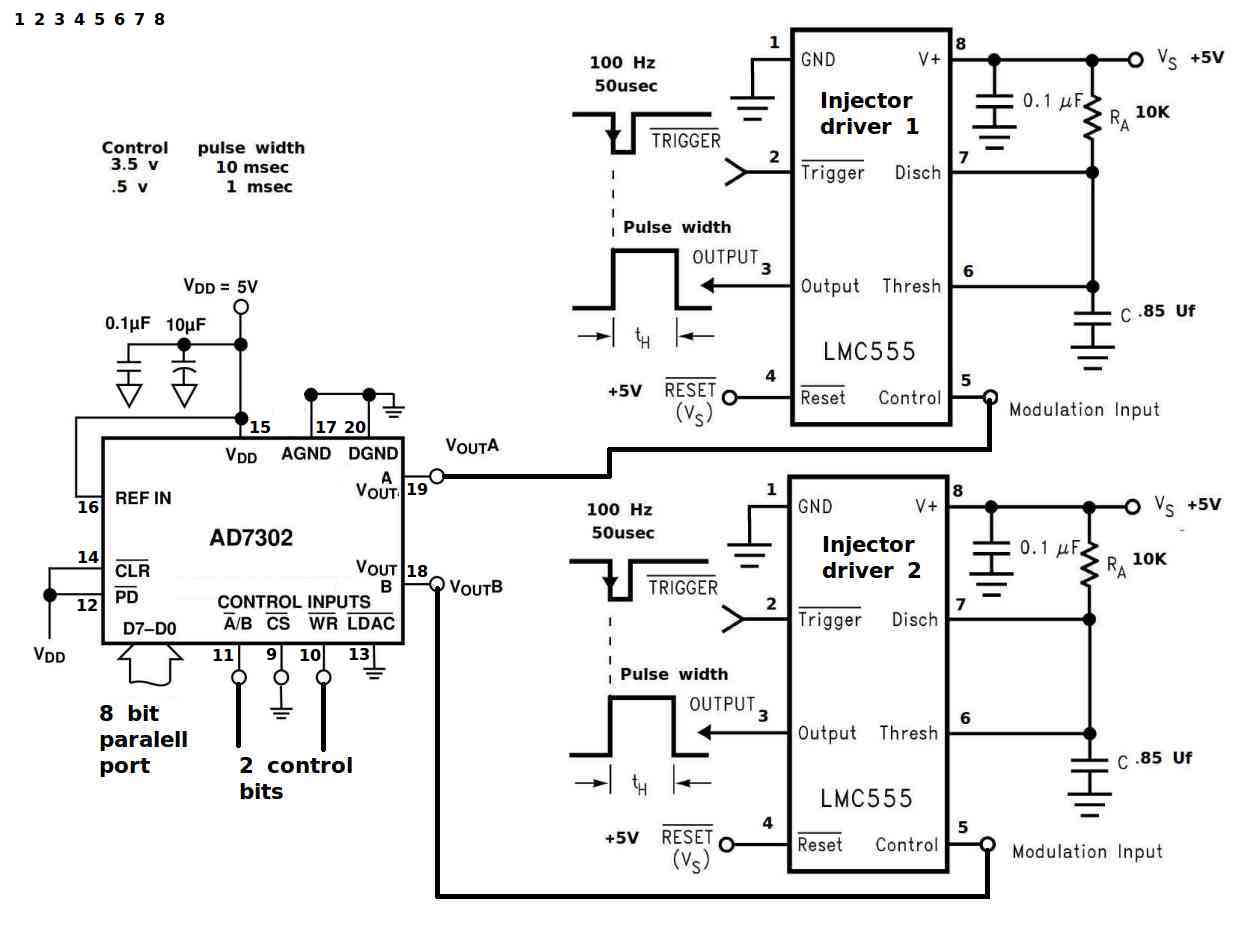
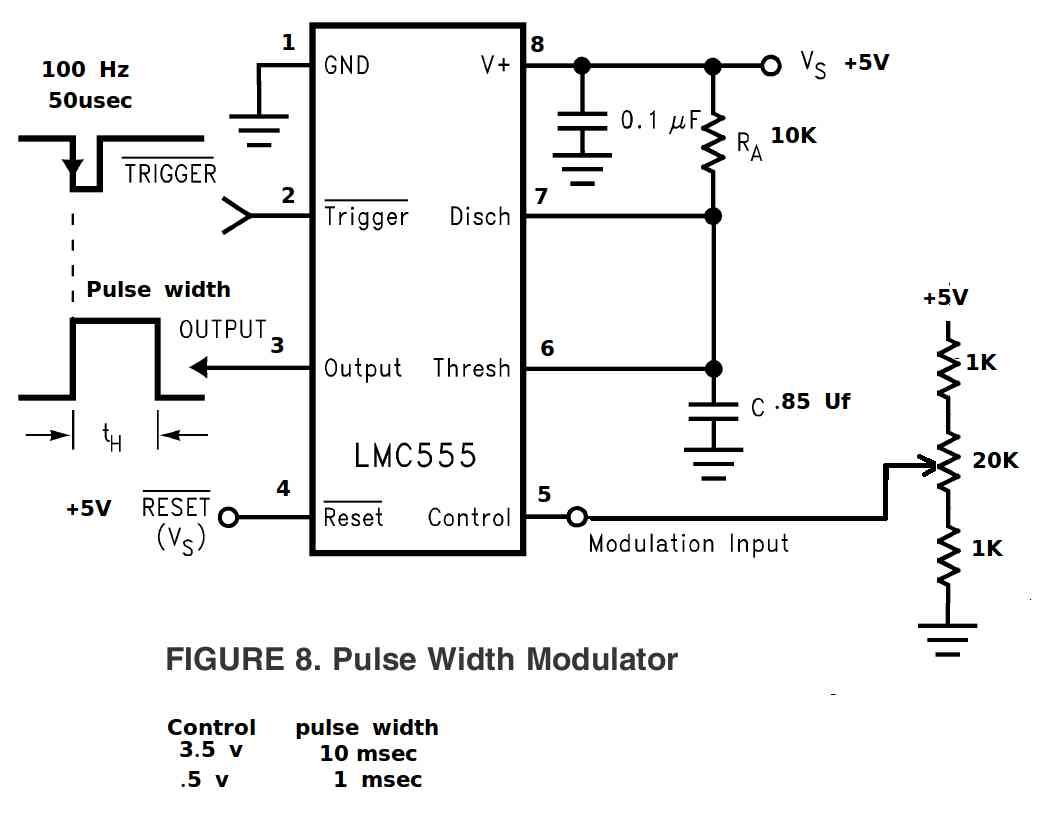
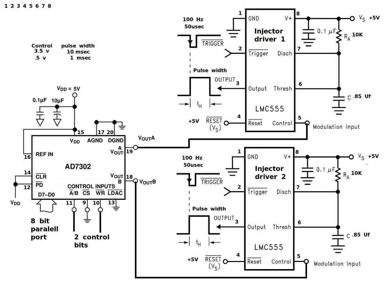
This circuit does the same thing but as long as
you want to what ever you want.
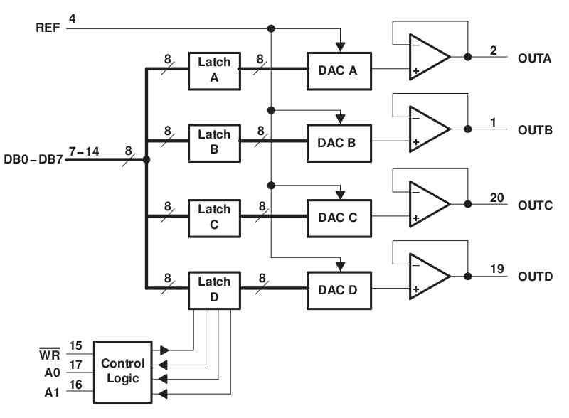
It requires an 8 bit port for two injectors
but as I recall the same D to A is available
in a 4 channel version that will handle 4 injectors.
The fuel injectors will continue to work if it
still has power even though the computer dies.
It requires a 10 HZ oscillator (100 msec injector
window) but that could be done with another
555 or come from a Pin on the MM. The injector
pulse width can be updated ten time a second
or less often at your option.
The 8 bit port sets the pulse width to one part
in 256 but once that is done this circuit handles
the injectors from then on in the back ground.
This is a classic example how sometimes it is better to add hardware
rather than software on low volume computer based products. Software
cost and programming time becomes the greatest expense.
Paul Lamar
It just occurrence to me that this external 555 injector driver circuit
can expand
the dynamic range of the injectors more effectively than the built in
Arduino
and MM PWM facilities with their low freq limits of 33 HZ and 20 HZ...
In the case of the MM the chip can output a frequency
in the range 1 HZ to 20Kz. The same pins that are used for
the MM PWM can put out the frequency to driver this dual
555 injector driver circuit. The bottom line is a better EFI system..
TONE
TONE left [, right [, dur]]
This command will create two tones for the Colour Maximite that
will be outputted separately on the left and right sound
channels.
The tone is a synthesised sine wave and can be in
the range of 1Hz to 20KHz with a resolution of 1Hz and is very
accurate as it is locked to the PIC32's crystal oscillator.
When the frequency is changed there is no interruption in the
output so the output can be made to glide smoothly across a
range of frequencies. The playing time can be specified in
milliseconds and the tone will play in the background (ie, the
program continues running).
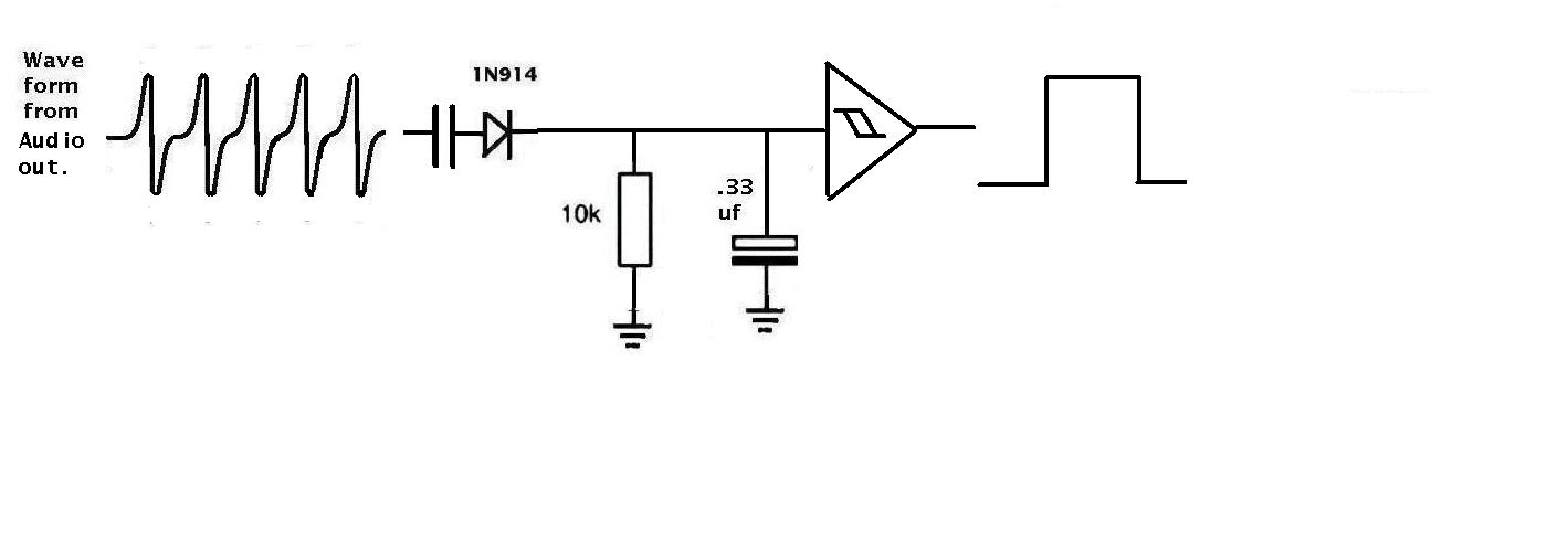
It ill take a transistor to amplify the tone and convert it to a square
wave.
You can have as little as one injection per sec if that works better for
idle. If you can tie this to RPM you can have a huge range
of injections. 1500 RPM at idle is 25 Hz. Divide that by 25 and
you get 1 Hz injection frequency or 1000 msec injection time.
At 7500 RPM you get 5 injections per second or 200 msec.
Tis is a far more flexible way to build an EFI.
Paul Lamar
The Rotary Engine News Letter. Powered by Linux.
If you want off the list PLEASE let me know and I will
remove you. ACRE NL web site.
http://www.rotaryeng.net
You Tube
http://tinyurl.com/beqqxas
Copyright 1998-2015 All world wide rights reserved.