The dodge 1500 truck rad core is 31 5/8" x 19 3/16" x 1", wouldn't
that give around 600 cubic inches? Or will that be doubled by having
2 of them in the cross counterflow? The newsletter reply below is
showing 465 cubic inches for that rad,did I pick the correct rad
measurements? Trying to size a rad to fit the cowl of p-port rx8.
Laying down vs upright on the cool side of cowl.
https://www.radiatorexpress.com/product.asp?part=2001+DODGE+RAM+1500+PICKUP++-+5%2E9+liter+V8+RADIATOR+STOCK+REPLACEMENT%2C+31+X+19+CORE&part_id=218342&aaia_id=1366590
The oil cooler we have is CXRacing with core of 13" x 9" x 2" which is
only 198 cubicinch. I read an old reply from Neil Unger that around
300 cubic inch for 250hp is good for oil cooling?
http://www.cxracing.com/mm5/merchant.mvc?Screen=PROD&Store_Code=CXR&Product_Code=OC-248-30-AN10&Category_Code=OILC
-Matt Boiteau
- Matt
Cross counter flow is a more effective heat exchanger.
Here is the sequence for welding the rads to make a cross counter
flow heat exchangers.
Butt tig weld the in and out tanks first by cutting off all tabs on
the rads.
Don't weld the in and out tubes on yet.
They will be marked for position on the tanks while on the aircraft.
Then the large holes for the tubes will be cut and then the tubes
will be welded over the holes. The tank design will vary depending
on cool side mounting or bottom mounting. The TTC is a bottom mount.
Most other aircraft use a cool side mount. The 3 rotor allows longer
rads to be used. Put the diffuser between the rads and the engine.
See my book How to Cool your Wankel for more info.
After the tanks are done (with out the holes and tubes) bolt the rads
together with the wood strips leaving 1/2 to 3/8 of an inch between
in and out tanks.
The idea here they must not touch each other. The wood strips are
heat insulators between the two rads.
Then weld an aluminium strip 1/2" to 3/8" wide at the other end.
Finish by boxing in the other end (the front end).
Weld on them some and let the rads cool some what. They are brazed
together at only 1100 F so it is important to not get them too hot.
Wet rags around the ends of the fins and tubes might help.
Here are a bunch of pictures attached. The JPGs were Dodge Neon rads
and not the truck rads. The TTC rads will be welded soon.
Apparently when Mercedes owned Chrysler they implemented some up to
date heat exchanger technology. IMHO Chrysler rads are now the best
from an efficiency point of view I have found so far. Honda also
uses up to date tech but they are more expensive.
Paul Lamar
What about a dual pass rad already done?
http://www.jegs.com/i/Allstar-Performance/049/ALL30048/10002/-1
-Matt Boiteau
It will probably work but you will be paying a weight and drag
penalty. I don't know how much on the drag penalty. We don't have
any comparison data on the drag yet. The weight of the core with
water will be at least 150% of the cross counter flow Dodge truck
rads.
Paul Lamar
For maximum efficiency, you don't want to use the flow pattern
described in their (Allstar's) text, use the pattern from Paul's
book. The top core (or first core exposed to cooling air) is the
second core the coolant flows through.
This better utilizes the Delta/T thermal transfer to the cooling air
flow. Read Paul's book for counter cross flow cooling theory.
C. Smith
Craig, can you send me that Allstar text. I found their web site but
I can't find anything about that. Apparently they use two rows of one
inch tubes . The Dodge truck rad is one row of .7 inch tubes.
http://www.allstarperformance.com/instructions.htm
In theory one could cut the All Star rad apart into a top and bottom
for a cross counter flow reconfiguration. That would give more core
volume if two Dodge truck cores were not enough core volume .
Slightly less efficient however.
The basic idea is you want as large a frontal area you can fit in the
cowling with core volume of about 500 inches. The Dodge truck core
are about 465 cubic inches and will probably work with 250 HP. We now
have about 930 cubic inches in the time to climb rad which I am
guessing will be good for about 500 HP.
I suspect the time to climb cross counter flow rad is not enough core
volume for 650 HP and we will have to spray cold water on the
assembly.
We used to think we needed 650 cubic inches for 250 HP and that was
before we discovered the much improved Kays & London wedge
diffuser.
Ian in Perth Oz did some experimenting with a Kays & London S shape
diffuser lying on it side and was able to reduce the size of the air
intake to 10 to 15% of the core frontal area. That, in theory,
reduces the cooling drag. Ian routinely flies around the outback.
Ian has built two RV6's powered by rotaries. The first one crashed
when a hose blew off a rad with out a bead on one of the tubing
ports.
Paul Lamar
Do we have any more pictures of Ian in Perth Oz, S shape diffuser
lying on it side ?
-Matt Boiteau
None with the cowl off.
Paul Lamar
The problem with dual and triple pass radiators is that they use the
same air temperature across the entire surface. Coolant flow rate
will be high which is good for turbulent flow unless they use a
double or triple core. The cross counter flow lets the coolant spread
out across the entire surface area in a single row radiator. Then
turns after one pass and returns through the second core. The hot
coolant in the first core is cooled by warm air used to cool the
cooler coolant in the second core. Same "frontal" and surface area as
a single radiator with a two row core but should give a higher delta
T. Should provide better cooling in marginal operating conditions.
For space constraints where the thickness would not pose a problem
you could build a three pass cross counter flow.
Dale Davies
The coldest air goes through the coolest core first. That maximises
the average temperature differences to maximise the efficiency of the
heat exchanger. Heat transfer rate is directly proportional to
average temperature difference. All this is covered in my book How
to Cool Your Wankel.
Dale please add your new message to the bottom of the forwarded
message. Like this. Make it look like this message.
Paul Lamar
I'm all for cross counter flow, I was just trying to understand math
between all these posts. *generally it looks like for 250hp P-Port,
500 cubic inches for water and 250-300 for oil ?
The truck rads mentioned, show the core being 31 5/8" x 19 3/16" x
1", Isn't that around 600 cubic inches? The older post is saying 465
cubic inches are the truck rads. Since there is 2 rads, do you double
the cubic inches (ie, the truck would actually be 1200?) Or was the
post getting confused with the smaller dodge neon rads, I'm not sure
their size/core.
I'm about to weld up the motor mount and trying to judge the size of
rads.
- Matt Boiteau
The Dodge truck rads are not quite one inch thick. I would guess the
core is closer to .75 inches.
One is all you need for 250 HP. You don't need cross counter flow
with that rad. The trouble is it is a bit too long to fit the Tango
cowling.
We used Dodge Neon rads in a cross counter flow in Alex Molteno's
Tango. I forgot the dimensions but they are quite a bit shorter than
the truck rad. Thin cores are the most efficient.
Paul Lamar
The Dodge neon rads measure 14"x 24.5" x 0.650 (fin surface area)
with about 0.5" extra sticking out on each side for the top and
bottom tanks.
I have a CX racing 30 row oil cooler, same oil cooler Tracy has on
his 3 rotor rv8. Its going back a few years now but I believe Tracy
said it cooled fine up to about 90F ambient after which he reduced
power to keep oil temperature in check.
Not a real problem with a 300 HP engine on an rv8, i imagine this is
why he never felt it necessary to change it. The only difference is
Tracy's cooing is dialed in. Mine won't be initially
My plan B is a larger Modine cooler of it doesn't work,
Alex Molteno
My plane is the same as Alex Molteno (He's the guy that got me started with
a rotary), but I added 3" lift to the whole fuselage giving me more
headroom. Consequently, more room under cowl too. I'm looking at doing a
truck rad (or similar) to the bottom of the cowl. Alex barely got his
crossflow dodge neon rads to fit.
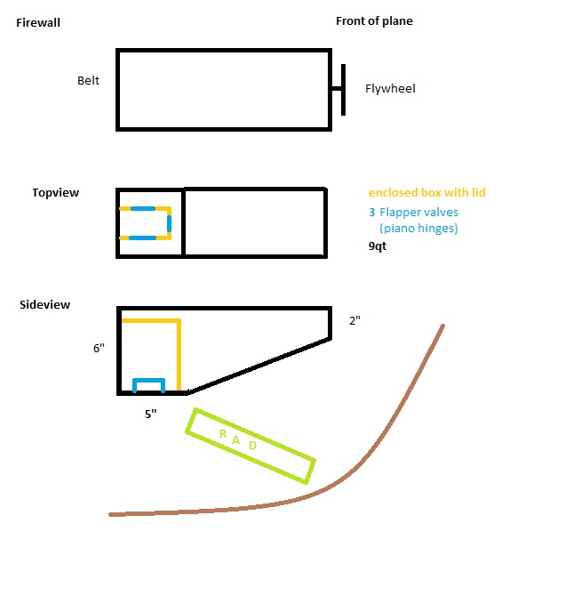
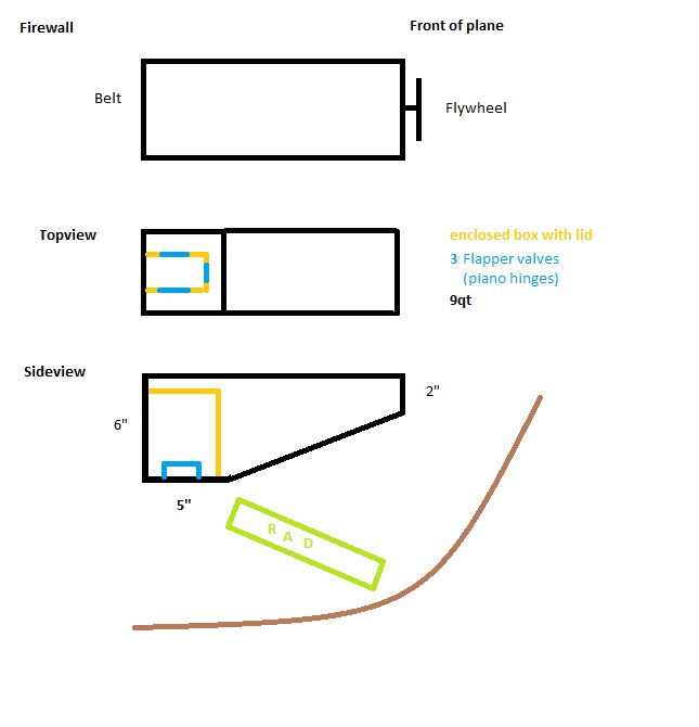
Kicking around the idea of changing the oil pan to wedge shape. Also adding
a box with flapper valves to keep the oil from moving around away from
pickup tube. Would it make sense to have the box fully enclosed with lid so
any foaming on top of the oil won't enter?
Please ignore my MS Paint skills. I haven't learned 3D drawing programs yet.
- Matt Boiteau
Unless you slip or fly inverted the oil in an aircraft engine always
stays in the bottom
of the pan. Side loads are not normally developed in an aircraft.
Paul Lamar
The Rotary Engine News Letter. Powered by Linux. If you want off the
list PLEASE let me know and I will remove you. ACRE NL web site.
http://www.rotaryeng.net You Tube
http://tinyurl.com/beqqxas
Copyright 1998-2016 All world wide rights reserved.