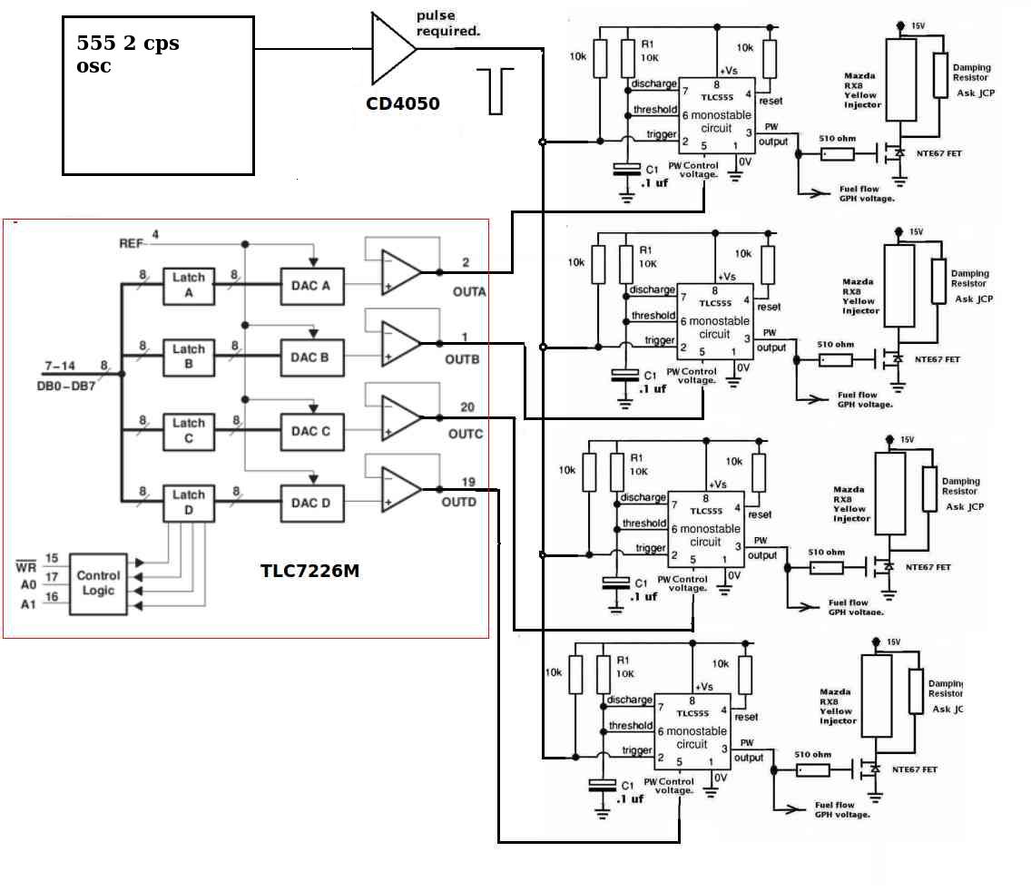
Here is a pre lim design for a Maximite or Arduino
shield that off loads the EFI injector control stuff
to leave more time for EFIS. Four injectors each
can be set up differently. Once set up the engine
will run for hours with no processor intervention.
It use the CMOS 555 in PWM modulation mode.
Paul Lamar
Nice work Paul, a DAC running the PWM with it only receiving updates
from the ecu.I do not think it will unload duty from the ecu, the ecu is
still generating the signal to the DAC, plus monitoring all the inputs
i.e. rpm, temp, afr and such. If you wrote in a condition to the loop
that it only sends updated signals from steady state it would just load
up the processor with more code to act on.
The external board is what I am also doing but the board can also run
the ignition and injectors without the ecu. I have changed the design a
bit to include opto couplers to protect the ecu and the driver boards,
with logic controlled SSR's that default to the crank signal to the
driver boards in case of failure of the ecu for any reason.
I have ran it on the bread boards being driven by the aurdino and it
works good in simulation. The new boards are ready to prototype but it
is going to have to wait a few weeks.
Oh here is a nifty little project I did this las week one evening after
dinner. A very small compact Oscilloscope, I have been using to check
injector scheduling and duration during the simulations. They are a kit
from Sainsmart, $22.00
Davd Jr.
The DAC has four 8 bit latches. When you send them a byte the related
DC output voltage stays constant until you change that byte. This gives
pulse width resolution to one part in 255.
The PWM 555's get a trigger pulses from the CAS so as long as the engine
is turning
over fuel will be injected. I will add ignition circuits that will put
out the required
4 ms dwell pulse for modern coil on plug ignition systems. Plenty of room
still on the PCB shield for that. Basically four more 555's in one
shot configuration.
That will require attention form the processor every rev but the code is
simple
and short.
Paul Lamar
Sounds good, solid approach. Is the 4ms the required dwell for the LS1
coils?
Is this for the ignition, the same approach you proposed for the
ignition firing
several times on each combustion cycle? I think you has mentioned 3 times
each combustion cycle, so 9 times each crank revolution?
I remember seeing something, I think it was a schematic you had drawn up
showing a optical trigger for the rotary, with 3 trigger holes every
33.3 degrees?
What would be the rpm limit you could do with this setup?
Oh, found it.
David Jr.
Yes the 4 ms is for LS1 and Mazda RX8 stock coils. These are lower cost
than my high speed coils.
That one is obsolete.
Yes I use a high speed optical trigger that fires the plugs up to 5 or
6 times
at 8000 RPM. It requires my patent pending high speed coils. We should know
if the patent is granted in April. If not we will modify it and resubmit.
You can also fire my coils with any computer. They can be fired as often
as 5 degrees apart
5 or 6 times at 8000 RPM. The trigger pulses can be as little as 2 usec
wide.
The energy is very high as you can tell from the attached mp4 video.
This will ignite paper in milliseconds. Always a good test for sparks.
The wiring is all SMA coax as the wide spectrum is high frequency on the
order of
Mega hz.
.
Make sure you have the sound turned up for the mp4 video :-)
Paul Lamar
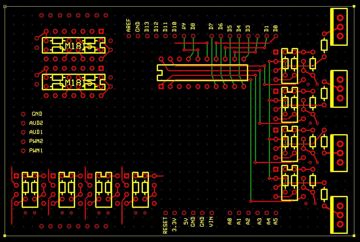
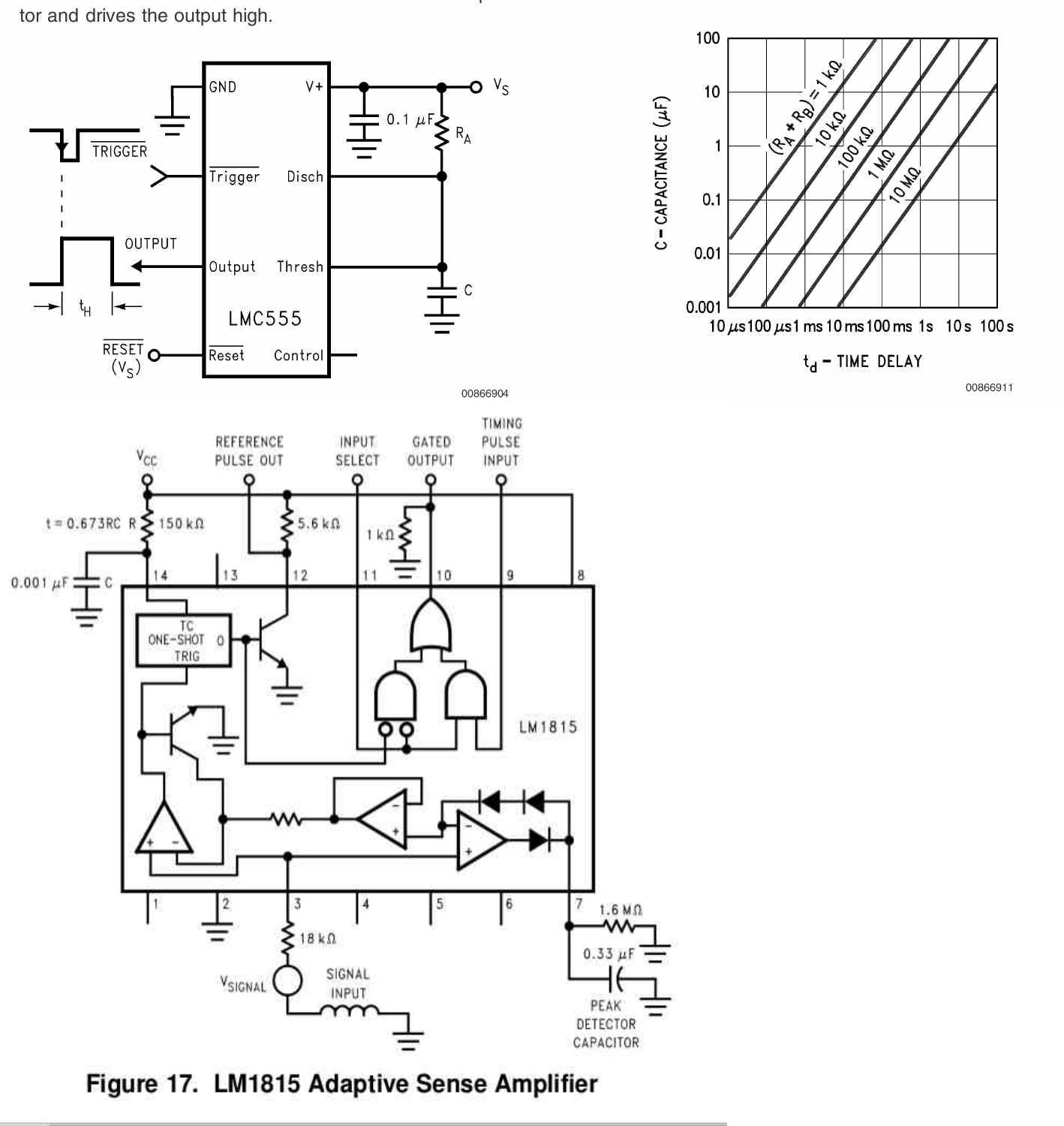
This is latest iteration of the shield. I was able to get two LM1518 on
board. This is
very popular analogue chip that conditions a standard reluctance sensor.
These are wildly used for ignition triggers, cam shaft angle sensors
and wheel speed sensors for ABS.
I also have four 555 one shots for the stock ignition coils and the
Injector FET's,
One of the tricks is put the 1/10 watt resisters on the back side of the
board. The density is almost the same as surface mount with out the
drawbacks.
A 3 layer board also works great with power and ground planes.
Third for the circuit.
Paul Lamar
The Rotary Engine News Letter. Powered by Linux.
If you want off the list PLEASE let me know and I will
remove you. ACRE NL web site.
http://www.rotaryeng.net
You Tube
http://tinyurl.com/beqqxas
Copyright 1998-2016 All world wide rights reserved.

