On Sat, 5 Mar, 2016 at 12:10 PM,
rotaryeng@earthlink.net
<
rotaryeng@earthlink.net wrote:
I am thinking about building a Reno Racer. We need about 800 to 1000
HP to blow the rest of those guys into the weeds :-)
First hurdle is coming up with a gear box. I can't afford $35.000 for
a bell final drive so I investigated the Allison 1000 truck
transmission.
Rumour had it it was 4:1 but that is not the case for a single
planetary set. P3 on the Allison is 3:1 when you hold the ring gear
fixed, take power out of the planet carrier and put power into the
sun gear. The output will rotate in the same direction as the
engine.
You get the ratio by dividing the ring gear diameter by the sun gear
diameter and adding one.
Here is a picture compared to the Ford unit most people are using
now for most rotary powered air planes.
Looks good for a 1000 HP 3 rotor engine.
A lot of the stuff attached to the ring gear will be machined away.
Paul Lamar
I have decided to build our own planet carrier out of 7075T6 and add
two pinions. Six total up from four. 50% more torque capabilities.
The Allison planet carrier is too hard to machine.
The planet parts are low cost. There are a million Allison 1000 out
there.
Here is what it will look. We will keep the .75 dia. planet shafts
and EDM a 1/2 inch hole in them for the prop shaft flange. Hardness
and smoothness are retained. Lower cost than making new shafts. The
back of the planet carrier is smooth for a pusher thrust bearing.
The Allison has a much better input shaft and the required splines
to the sun gear for our purposes than the Ford.
I talked to Kyle Mohan yesterday about his 3 rotor Drift engine
making 800 to 950 HP with side ports no less. It is running on
gasoline. The turbo charger is smaller than the time to climb turbo.
A Turbonetics GTX 750. He has 20 races around the world on the engine
so far with out rebuilding it.
Much thanks to my auto transmission expert Donny Caccamise that has
helped us over the years.
Paul Lamar
The prop situation is not as bad as I thought. Here are some charts
generated by a BASIC program of tip speed verses RPM. We will see
what RPM the time to climb engine achieves to see how well the Catto
84 inch prop deals with tip speed. This also helps the gear box as
the shaft stress is reduced with a constant 1000 HP at a higher shaft
RPM than 2000. The shaft diameter is between 50 mm and 60 mm
depending on what needle bearing I can buy.
I have yet to calculate the tip speed at 400 MPH AC speed. That can
be done with a modification of the BASIC program. It will be a max of
1.3 times the radial tip speed.
If we are lucky the TTC engine will achieve 7500 RPM with the 3:1
gear box. I can hardly wait :-)
More on this soon.
Paul Lamar
Paul, We changed the nose case on Steadfast to speed up the prop from
.7 to .9 mach at the tip at race speed. It didn't add any speed! It
made the plane smoother as we were able to run a better prop
combination, but as it came out, that same prop on the slow nose case
gave us the same speed. If you want to go really fast at Reno, think
three things....... aerodynamics, aerodynamics and aerodynamics. Drag
reduction is the easiest way to go faster! The brute hp method works,
but at a price, and drag reduction has far better yields. A very low
drag airframe will beat them at much lower hp numbers. Not that I
don't like HP, but I can tell you for a fact where we found the speed
in Steadfast. Larry Child
Well that is fine but I don't have the money or time to design a new
Sport Class racer. As I understand the Sport Class rules you need to
sell x number of kits to qualify.
I know top speed is the cube root of HP.
I was planning on buying a flying Glasair and using that. I think a
GlasAir is now going over 400 MPH. A few aerodynamic tweaks may be
possible.
I will be happy if we can just stay with them :-)
Weight is also a big factor as when you are pulling a steady 3 or
4G's
Paul Lamar
Larry, do you have my book How to Cool Your Wankel ?
If you apply the Kucheman & Webber curve on page 29 to the inside of
your cowl you can cut down on some of the opening area and in theory
reduced the cooling drag. This was done on late radial engines like
the Super Connie.
Paul Lamar
Paul, Don't think I have it. I have many of the old docs from NACA on
cooling the radial (and water cooled) engines. There was great
research done late in that engine era that never went into production
as the jet age took over. We used the data to redo the engine cooling
on Steadfast and gained lots of speed. The other area we gained lots
of speed was getting the airframe straight so the plane flew with no
trim at speed. On sport class airplanes there are many areas to
reduce drag and I will go over them when you are here. I have a
friend who does drag reduction design work that is very interesting
and has been used on several very fast sport planes as well as the
jet class. Larry Child.
OK Larry Thanks.
Paul Lamar
Here is the effect of 400 mph aircraft forward speed on the prop
tip vector speed at various RPM's and diameters. It is the square
root of the sum of the forward speed squared and the square of the
tip tangential speed.
QuickBASIC is invaluable for these kinds of calculations. I have an
old windows computer that still runs QB in a command window.
Looks like we will need 5 wide blades at 2000 RPM and 68 inches in
diameter to absorb 1000 HP. Perhaps we can get a surplus C130J prop
:-) I keep saying the Mazda Wankel is as good as a turbo prop.
We also need a 4:1 gear box but we can get along with 3:1 if we up
the boost. This will be a severe test of the Mazda Wankel structural
strength.
My guess on why that GlasAir is going so fast in the Sport Class is
he has geared his engine about 2 to 1 and he is running it at 4000
RPM or above.
Paul Lamar
FYI, that transfer case I was talking about comes in a 4:1 version.
Everett Rankin
"The NP241 was manufactured with drop output on both drive and
passenger side and has a low gear ratio of 2.72 to 1. This unit has
combination of 2WD, 4W high and 4W low. The units are provided with
various front inputs, output splines and utilizes a both fixed and
rear slip yokes. "
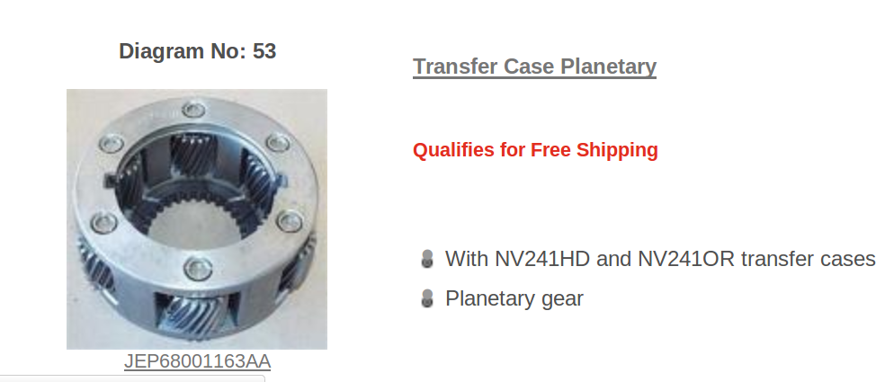
The information I have is 2.71, You can tell by looking at the
picture of the planet carrier. Divide the OD by the ID and add 1.
High is just one to one.
Paul Lamar
The version in newer Jeeps is 4:1.
http://www.advanceadapters.com/tech-vault/5-new-venture-241or-roctrac/
Everett Rankin
http://www.4wheelparts.com/hardparts/HP_PartList.aspx?hpDID=346
"The NV241OR (Rock Trac) transfer case came out in 2003 with its all-new
4:1 low-range ratio from the factory. It is used in the 2003 to 2016
Wrangler Rubicon’s only. To identify if it’s a NV241OR (Rock Trac) the
round ID tag on the back half of the case will have an OR (off road)
after the NV241 number. If no tag is present look at the input side of
the housing it will have additional overlap around the input assembly.
This was required to house the larger planetary gears, and the rear case
half has generous ribs to handle the increased torque afforded by the
lower gearing."
This is a picture and it is not 4:1. If the ring gear and OD of the
planet carrier
is 6 inchs the ID MUST BE TWO INCHES!!!!!
This is not TWO INCHES!!!
The picture they are showing on the web site is NOT a 4:1 planet carrier!
Get a picture of the planet carrier and send it to me.
Paul Lamar
The Rotary Engine free News Letter. Powered by Linux. If you want off
the list PLEASE let me know and I will remove you. ACRE NL web
site.
http://www.rotaryeng.net You Tube
http://tinyurl.com/beqqxas
Copyright 1998-2016 All world wide rights reserved.