Yes! Those are just the renderings. Pick out what you want and I
will send the IGES.
Paul Lamar
Hi Paul, I think those AL housings appeared while I was away. Could
you send me some detail of the wear plates and the Al housings; an AL
center hsg would sure cut some weight out of the total engine weight.
I have a friend who has just retired from his engineering business
and has kept a lot of his machine tools so I have access to CNC
mills, wire cutters and lathes. Rs, Dave McC in Perth
Do you have access to Rhino 3D drawing program? There is no such
thing as a 3 view drawings with dimensions these days. Everything is
done with IGES files. The dimensions are hidden.
The wear plates can be made in at least two ways. A stock cast iron
end housing can be cut down or a new one made of of hard 4130 sheet
laser cut and then chrome plated like the stock rotor housing.
Too bad Australia is so big. Neal Unger in Parkes NSW is doing a lot
of the same things. Neal has a p-ported-13B powered Glastar flying.
Neal is also president of the Sport Aircraft Ass. of Australia.
SAAA.COM You guys should work together. Oz is in real need of a one
rotor all aluminium LSA engine as the Jabiru is struggling.
http://www.aviationsafetymagazine.com/airplane/LSA-Engine-Safety.html
I'll send you Neal's email address by private email.
Paul Lamar
Paul et al,
I have what is probably a basic question.
I have often read that a propeller induces adverse vibrations into a
drive train and that a belt driven PSRU is the way to isolate those
vibrations from the rest of the components and engine in general
while allowing the propeller and engine to each operate in their most
effective rpm range. Yet I also see a lot of planetary (and other?)
gear drive units, especially in the information shared here, that
would seem likely to transmit those propeller vibrations. So in the
applications being discussed here how is a direct drive permissible?
Is it because the aircraft (e.g. the time to climb) are limited
purpose and limited life and thus not likely to be adversely affected
in the time they are operational?
Just curious and hoping to understand better. Thanks for any
responses!
Brad Chubb
The planetary was universally used in aircraft engines for years.
Only in WW II was a spur gear used in the water cooled V12's. All the
radials had planetary gear box's including the largest aircraft
engine ever made in quantity. That was the P&W R 4360 Wasp Major. It
had 18 planet gears. The latests in large P&W turbo fan engines for
airliners is a planetary gear box that is 98% efficient.
Direct drive requires a lot of displacement for a limited amount of
HP. The 2 rotor rotary engine is small displacement as aircraft
engine go at 160 cubic inches. However the time to climb engine is a
record amount of HP (650) for it's weight of under 250 pounds with
gear box.
BTW The rotary is also a record amount of HP per cubic inch of
displacement at 4 HP per cubic inch. The former record holder was the
Offenhouser race engine at 3 HP per cubic inch.
The TTC record holder Grumman Bearcat had 2 pounds per HP to lift
while our TTC aircraft (Vans RV4 basically) only has 1.5 pounds per
HP to lift. Weight per HP is the name of the game in high climb
performance. Ask any truck driver :-)
We are about done with the installation and we are waiting until Dan
Gray gets back from vacation to test run the engine on the aircraft.
Paul Lamar
Paul, The interesting thing I see with the P&W planetary, (besides
the hyper-expensive herringbone cut gears), is the fact that that
planetary must be fully assembled before any other components can be
added. You cannot slide in the sun gear or put on the planet carrier
with herringbone gears. The planet shaft must be removable. They are
even better than straight cut, (stronger for their diameter), but
you need to be a government funded project to afford them!
Bill Jepson.
One never knows. New methods of making things are invented all the
time.
I just found out fender dies are now EDM'd. A big block of carbon is
3D NC milled and then it is sunk into a big block of steel with EDM.
Cheaper than 3D milling the female steel dies directly. Also a better
finishing with no hand polishing of the female steel die.
Paul Lamar
Paul, just so that this thread doesn't stay without comment on Brad's
question, there is a lot of misinformation on the net about propeller
gearboxes, much of it wrong.
The propeller does not induce vibrations. Once spinning, it
represents a nearly constant inertial moment. The problem is that
combustion events in the engine deliver pulses of power to that
inertial load through a spring. The spring is made up of all the
parts between the combustion and the air that the prop is pushing.
The combination of the spring and the inertial load define a resonant
frequency just like a clock pendulum has. If you excite the spring
near that frequency, the energy will stay in the spring rather than
coupling out to the air, and each combustion event adds to the energy
stored. (If you put pulses of energy into a clock pendulum at other
than its resonant frequency, it doesn't move much, but if you do it
at the right frequency it will keep swinging with very little energy
input.) The excursion of the spring will increase for each power
pulse until something breaks. You can use a planetary, or plain
gears, or belts, or chains, each one can be designed so this doesn't
happen. Belts in fact are nearly as stiff as gears, and usually
stiffer than any kind of shaft driving the pulleys. The whole system
has to be designed together so you know where the resonances are,
and if they are in the operating range of the engine you incorporate
means to detune them if things get too excited. Every successful
propeller gearbox addresses these issues in a systematic way,
there's no shortcut.
For Brad, Paul's TTC engine has a very stiff and robust planetary
gear set between the engine and the prop. I don't know for sure but
would expect that the resonant frequency of that system is far below
the normal operating range, somewhere in the high idle range. They
will go through that range quickly on startup. During the brief time
when the engine is operating at that range, the rubber will deform
and break the resonance for at least a few cycles. It does not damp
(attenuate) or absorb much power; if it did, it would burn up in an
instant. Above that frequency the rubber will not be compressed and
will behave like a solid block.
David Josephson
Every one we ever tried so far, not including the TTC, resonates
about 1800 engine RPM. This includes all of Ross's, Tracy's and, of
all things, the Rotomax. The Rotomax had a spur gear. I don't know
why. Even my direct drive C 182 O-470 shutters when it is shut down
between propeller 500 RPM and zero. We idle the rotary at 2000 RPM
to avoid this. Even on landing as the prop is only turning 650 RPM
or so.
We are not sure what the TTC is going to do but my money is on 1800
RPM :-)
Paul Lamar
It has nothing to do with the gear type. Without doing the
measurements I would bet that the prop inertia (divided by the gear
ratio) and the spring constant of the eccentric shaft are the
defining moments. This is a really simple problem; to read about this
magnified to nightmare proportions, find a paper on the web
"Development of the R-2800 Crankshaft." Your O-470 has a resonance
below 500 rpm that's probably set by the crankshaft compliance and
the prop inertia. The bigger 520 engines have pendulum absorbers to
reduce it. Corvairs are at around 1100, Rotaxes around 1600. There
are some weird ways around the problem; the MW Fly engine from Italy
kills the compression by changing valve timing so the engine can't
produce any power in its resonance range.
David Josephson
My first O-470 had one pendulum damper. The one I have now has two.
The input shaft on the Ross and Tracy was only one inch in diameter.
Chris Hoskins input shaft is 1.5 inches in diameter. Since the
torsional stiffness is proportional to the fourth power of the
diameter that is five times stiffer. However Chris's rubber coupling
is going to be adjustable and far more effective than Tracy's. Ross
used a stock spring clutch plate.
Paul Lamar
I have read here and there that the mathematics needed to design a pendulum
damper can be found online, but I have never been able to find it. I
have the
Kerr-Wilson book and others on torsional vibrations, but they are almost
unusable to me. I have considered getting tutoring from a local university
prof or working engineer when the time is right. Anybody know of a SIMPLE
mathematical treatment for pendulum dampers?
Gene Kahn
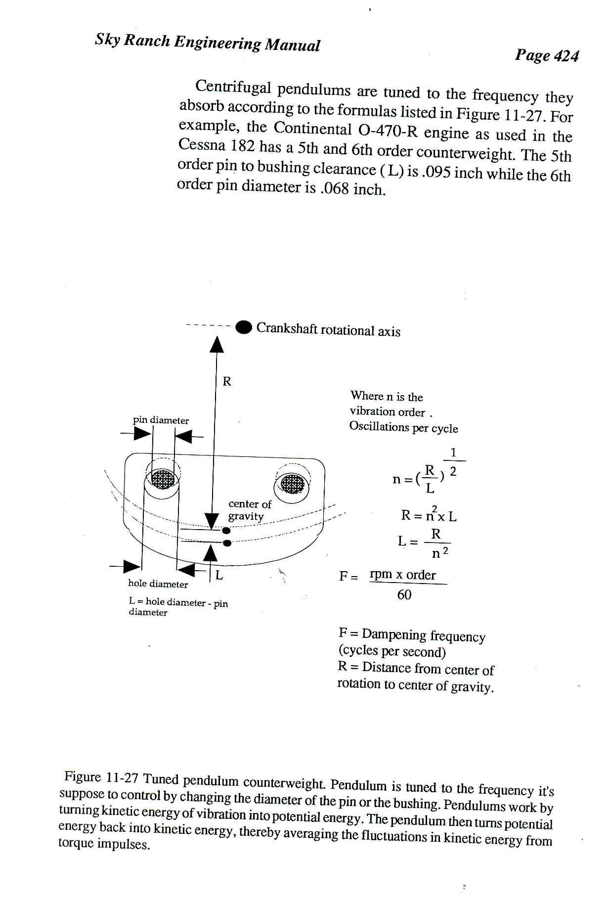
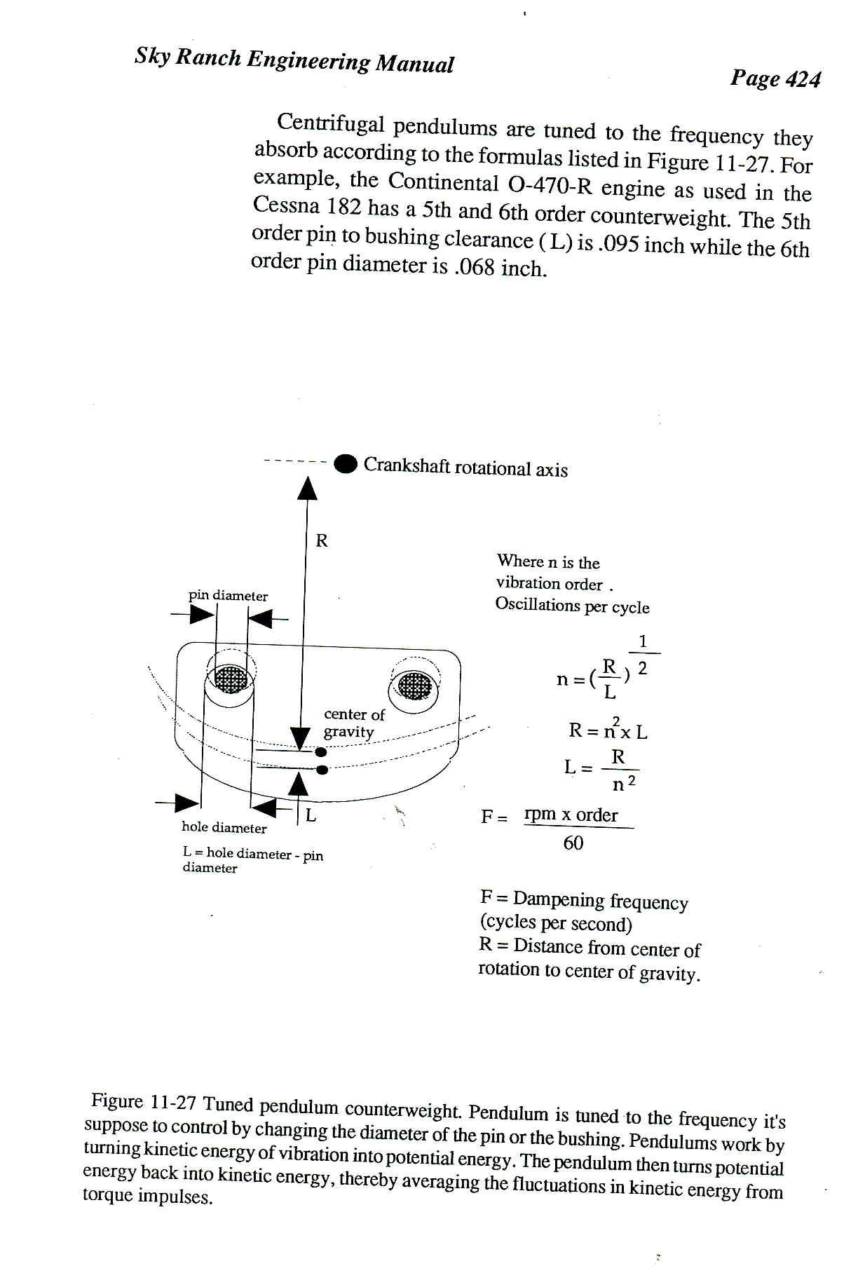
The first thing you need to know is the resonant frequency of the
shaft you are trying to damp. That info is hard to find for most aircraft
engines and it depends on prop inertia.
Then know that a point on the shaft some distance from the center is
oscillating
back and fourth as the point rotates around the center of the shaft.
Here is a scan from the Sky Ranch Engineering manual.
Paul Lamar
The Rotary Engine free News Letter. Powered by Linux. If you want off
the list PLEASE let me know and I will remove you. ACRE NL web
site.
http://www.rotaryeng.net You Tube
http://tinyurl.com/beqqxas
Copyright 1998-2016 All world wide rights reserved.