I have simplified the program some what and speed-ed it up. I was
missing some of the compression pulses at 10 milliseconds.
Here is the new program with comments.
. Cls '.........................clear the screen
3 Open "press.dat" For output As #1 'open a file on the SD card
'..............................................................upper
and lower case does
'...............................................................not
matter in MM BASIC.
5 SetPin 9,1 '............set up pin 9 for A 2 D input 6 Print
"rotor 1" '......print on the screen 7 Print Date$ '.......print on
the screen 8 Print Time$ '........print on the screen
SetTick 10,30 '.....wait until 10 milliseconds has past
'............................and then go do it.
10 'bakgr '.........twiddle thy thumbs 15 GoTo 10
30 For x = 1 To 8 '....sample & record 8 readings as fast as
possible '.............................probably as often as a few
dozen microseconds.
press = Pin(9) Print press ; '.......print on the screen Print #1,
press; '.....record it Print #1, ","; Next Print '..............print
a carriage return on the screen Print #1, '...........record a
carriage return in the file
35 IReturn '......software interrupt return
Here is a picture of the output on the screen. These numbers need to
be doubled because of the voltage divider. As you can see there are
3 pulse in a row indicating this rotor is OK.
The numbers data file is an ASCII or txt file so you need to open it
with word pad. It is zipped because it would display on your cell
phone as one great big long message.
Paul Lamar
Hi again Paul Looking at the resolution of the chart, how about
changing the interrupt to 1 mSec.
Steve
Yes I think that would be better.
Paul Lamar
That works. One millisecond.
I installed a pot to check the A 2 D and it is working as
advertised.
I read the fine print in the sensor doc and .5 volt is as low as it
goes so subtract .5 from all that data I sent.
Please re plot it. I think that will look more reasonably. The span
is only 4 volts. so the divider will be 3.5/4 or 0.85 and not .5.
When all else fails read the doc :-)
Another problem is the throttle was not open so it had trouble
filling the chambers.
I have a plumbing problem so until I get that fixed more data will
have to wait.
Paul Lamar
Hi Paul
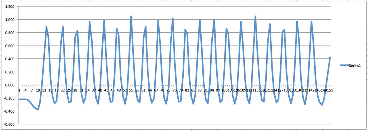
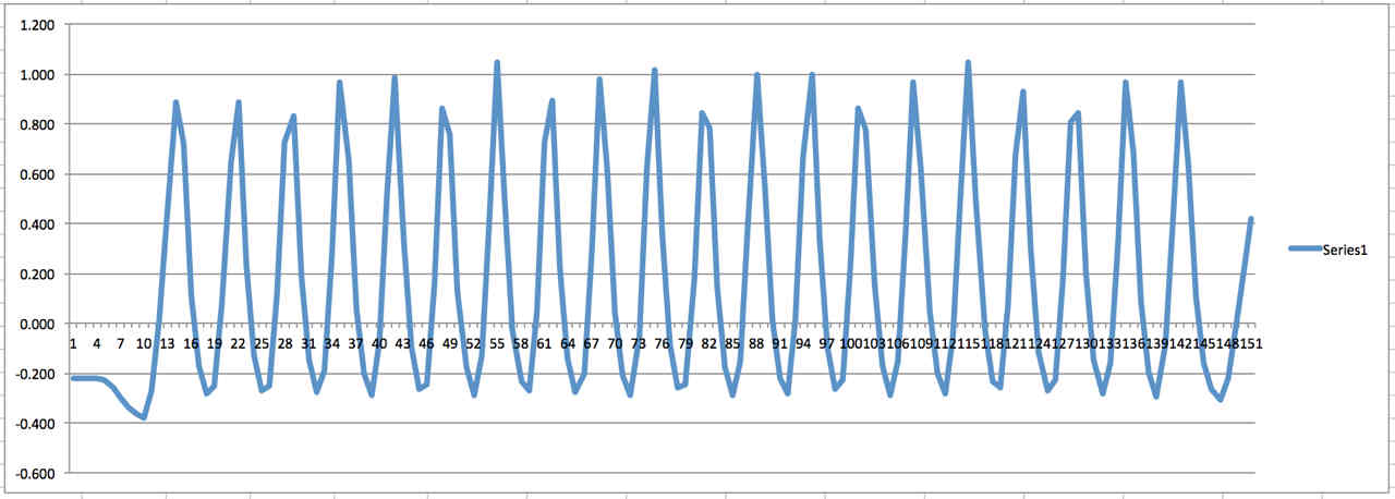
So to the raw data:
Average the 8 samples
Multiply by 4/3.5 to convert 3.3v full scale deflection to 4v
Then subtract 0.5 volts.
Plot looks like:
What is the ratio of volts to pressure out of the transducer?
1 volt = x PSI etc.
Steve
I think one needs to subtract the one volt first and
then double the readings. We are recording the doubled readings.
The first .5 volts in the sensor does nothing. Double that is one volt.
4 volts would be 150 psi. Pin 9 would would then see only 2 volts.
In other words if you see 2 volts on pin 9 it is 4 volts and 150 psi.
I'll change the resistor ratio soon. I am thinking 6.8K on the bottom
and 1.2K on the top.
At one Msec the plot will look more realistic with longer low numbers.
Maybe tomorrow I'll have the plumbing fixed and I can run it again.
I don't think we will have the new turbo til Monday.
Paul Lamar
The Rotary Engine free News Letter. Powered by Linux. If you want off
the list PLEASE let me know and I will remove you. ACRE NL web
site.
http://www.rotaryeng.net You Tube
http://tinyurl.com/beqqxas
Copyright 1998-2016 All world wide rights reserved.