Paul,
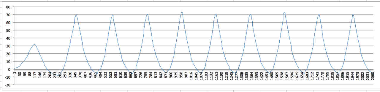
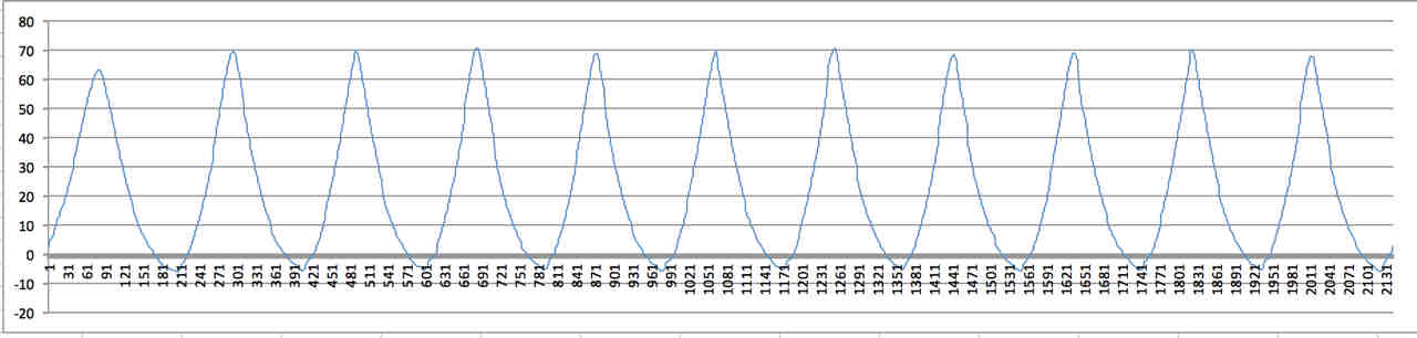
This is a composite of what my pressure traces look
like at 5000 rpm.
This is from a side-port intake and peripheral exhaust
rotary.
I added the combustion trace for reference.
The system I use can record 50K/sec and the data
becomes very dynamic....
the pressure peaks seem to slowly increase and there
position
retreats about 80 degrees between 3000 and 8000 rpm.
Barry Bordes
I am not sure what I am looking at here but there
appears to be something
seriously wrong with that engine. I suspect one or
more apex seals are
leaking.
Good engines are more consistent.
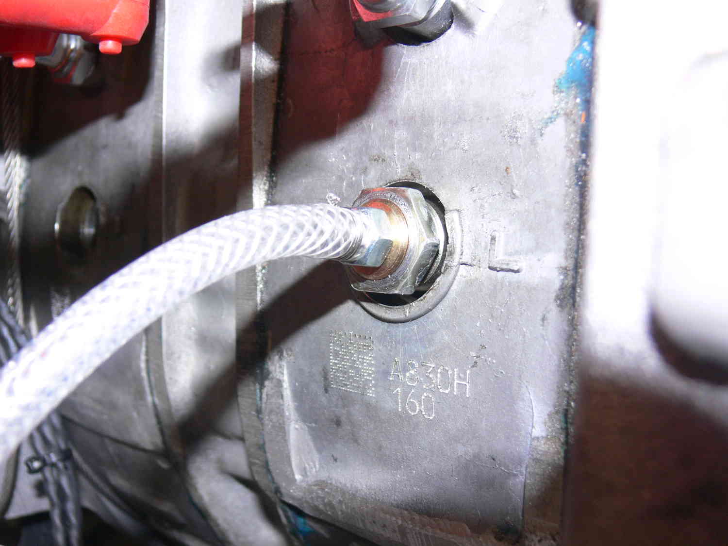
Take some pictures of where the pressure sensors are
located.
Please load that first picture into MS Paint and label
the lines.
Which one is intake and which one is exhaust?
What brand of data acq are you using?
The first two pictures are yours. The rest I took on a
P-port.
The sensors were looking at the apex seal oil holes in
the rotor
housing.
I just installed an exhaust pressure sensor on the TTC
engine so if all goes
well I will have some data on that.
Paul Lamar
Paul,
My focus was on overlap pressures in the
area between the ports.
The intake sensor is plumbed at the
front plate opposite the secondary port itself.
The exhaust was first tapped into the
exhaust sleeve area but because of a weak
signal was moved to the EGT port on the exhaust
pipe 2" from the flange.
The system is by TFX Engine Technology
The pressure sensors for intake and
exhaust are non-TFX. (TFX sensors are $1000
each).
I am using GM MAP sensors and have attempted to
scale them properly for the charts.
The taller trace is the intake.
Do you do Face Time? I could show you
the program results live.
Barry Bordes
That is very interesting to me Barry. I have
always wondered what went on in
that area. Due to the bath tub depression in the
face of the rotor there
will always be some over lap. I suspect the
inertia of the gases enter into the
successful functioning of the rotary. The analogy
is a turbo jet engine.
The inertia of the gases exiting the compressor
section cause them
to flow into the combustion chamber. If one looks
at it strictly from
a pressure point of view that may be misleading.
I would love
to see a flow visualization in that area.
So little is known about what actually goes on
inside a Wankel.
What we need is glass Wankel with a pulse of high
pressure colored
gas applied to the spark plug hole at the right
time.
There is a free idea for you Simon Saba :-)
I don't do Face Time. What is it?
Paul Lamar
----------------------------------------------------------------------------------------
We just ran the TTC engine with the new turbo. At
6700 RPM static and 15 psi boost
the exhaust back pressure is only about 3 psi.
That 1.25 inch diameter hole
in the exhaust manifold is keeping it down. That
means some mixture is going
out the exhaust.
6700 RPM static is more like it :-) It never
occurred to me to check the turbo when
we were only getting 5000 RPM static on the first
test run. The engine was and still is in perfect
condition as verified by our Maximite compression
tester. We will do a 45 degree angle
of attack test and then a short hop at SZP.
Paul Lamar
The Rotary Engine free News Letter. Powered by
Linux. If you want off
the list PLEASE let me know and I will remove you.
ACRE NL web
site.
http://www.rotaryeng.net/You Tube
http://tinyurl.com/beqqxas
Copyright 1998-2016 All world wide rights reserved.