The RX8 core is a good core to use as are Chrysler Doge pick up
cores. Large frontal area with thin cores. The Dodge core is 20" by
30" and is very very effective in a cross counter flow configuration
on the TTC engine. Two cores back to back.
Let's take the Dodge in a non cross flow config.
20 by 30 is 900 square inches.
We have learned more about this subject since Neil Ungar started
flying and on the time to climb engine. Neil complained about over
cooling. It appears we can reduce the intake area of the wedge
diffuser to 15%, of the frontal area of the core, from the 20%
recommended previously.
In other words 15% of 600 square inches is 90 square inches. The
core is 20 inches wide so the height of the 4.5 inches high and 20
inches wide.
Both Neil and the TTC rads are directly in the prop blast so if
that is not the case then you may note higher water temp when
taxiing.
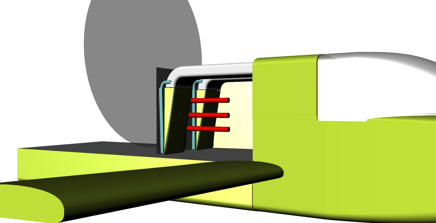
Here is the dodge core on top with the diffuser underneath. Yet
another 3D :-) It is far enough forward to give room for the intake
manifold behind it. This leaves room underneath for and oil cooler.
The exhaust out the back of the cabin may help to attach more air to
the aft sides of the cabin. This is a problem that was addressed by
vortex generators previously (or in addition).
Paul Lamar
Excellent recommendations, thank you! I was thinking of having the
radiators on the top/back (low pressure) of the upper cowling with a
long K&L duct. Your version may be easier. I will play with some
radiator models on the actual engine. The smaller the rad size the
easier it will be to fit. 20x30 will be a challenge.
In this model, it seems that two 20x30x1 counterflow radiators
would give a total volume of 1200ci? Is it correct that we need
about 600ci for water cooling and 200ci for oil? If so, I assume
that using cross counterflow rads would each need to be about 1/2
the Dodge size as long as I have 600ci?
My RX8 has twin oil coolers about 8x10x2. The single RX7 oil cooler
is about the same volume. The latter should fit up front if the
water cooler intake is a little higher.
Has anyone used 3D printing to create their engine cowling?
Scott Gettings
Those volume numbers depend on the thickness of the core. Thinner
core less cubic inches are required as thin cores are far more
efficient for a given volume. Dodge were leading the way with other
manufactures catching on.
This is a cross counter flow rad for a Tango
14" by 24" They are Dodge Neon cores.
Some what more compact at higher cost to make. You also need a
skilled tig welder.
-------------------------------------------------------------------------
Scott,
We should change the standard to square inches of frontal area
because all the recent cores are around 5/8 to 3/4 inch thick
including the RX8. Rad core frontal area is more correlated to
cooling than volume.
600 square inches frontal area for 250 HP single core. 2 x 300 square
inches for cross counter flow. Two Neon rads are about that. Maybe a
bit more so they should handle a mild turbo charge.
BTW have you considered a 8" prop extension to help the air stick to
the cabin sides? You can lesson the angel at which they go back. If
you go back at 7 degrees and then cut it off flat that will implement
the Kamm effect. Same as the recent Preuses.
Paul Lamar
Hi Paul, I noticed during my re-search on the Glass Goose that the
Icon A5 also has issues back in the cabin sides. They have also used
vortex generators in that area, on the test planes. The GG has the
lower wing and the landing gear that also adds to the problems.
Steve Steve Carlisle
Yes. It is a result of the side by side seating. That Icon is almost
a scam. Be wary?
With the Glass Goose it would not be that hard to change it to fore
and aft seating and narrow the cabin. That lower wing is necessary
to keep the prop out of the water spray which will destroy it.
Here are a couple of great books on seaplanes. Extensive discussion
of the unique design issues.
Paul Lamar
Correction fore and aft seating.
The Kamm 7 degrees does not work out well both side by side and fore
and aft.
The first 3D is side by side the rest are fore and aft.
Of course to build it fore and aft seating one would have to start
over. Not practical for those already built.
Paul Lamar
IMHO if I were designing a sea plane I would scale something that
worked well like some of the Dornier's like the DO 26. Google it.
Actually the Schneider cup racers found out a long time ago floats
were lower drag than sea planes.
I also think a coot is a better than a glass goose.
Paul Lamar
Hi Paul, I stumbled across this amphibian concept, made in
PlaneMaker, for Xplane. It likely has no turbulence issues, a lot
like the SeaRay amphibian. Applying this parasol wing and aft cabin
mods together with interplane struts would also lift the prop out of
the water, no need to put a prop dam on the empenage.
Inline image 1
Steve Carlisle
Looks like it violates the 7 degree rule.
Paul Lamar
The Rotary Engine free News Letter. Powered by Linux. If you want
off the list PLEASE let me know and I will remove you. ACRE NL web
site.
http://www.rotaryeng.net You Tube
http://tinyurl.com/beqqxas
Copyright 1998-2016 All world wide rights reserved.
On Aug 13, 2016, at 12:36 PM, Scott Gettings <
sgettings@cfl.rr.com
<
mailto:sgettings@cfl.rr.com wrote:
*Subject:* *Glass Goose Sea Hawker cooling systems.*
The RX8 core is a good core to use as are Chrysler Doge pick up
cores. Large frontal area with thin cores. The Dodge core is 20" by
30" and is very very effective in a cross counter flow configuration
on the TTC engine. Two cores back to back.
Let's take the Dodge in a non cross flow config.
20 by 30 is 900 square inches.
We have learned more about this subject since Neil Ungar started
flying and on the time to climb engine. Neil complained about over
cooling. It appears we can reduce the intake area of the wedge
diffuser to 15%, of the frontal area of the core, from the 20%
recommended previously.
In other words 15% of 600 square inches is 90 square inches. The
core is 20 inches wide so the height of the 4.5 inches high and 20
inches wide.
Both Neil and the TTC rads are directly in the prop blast so if that
is not the case then you may note higher water temp when taxiing.
Here is the dodge core on top with the diffuser underneath. Yet
another 3D :-) It is far enough forward to give room for the intake
manifold behind it. This leaves room underneath for and oil cooler.
The exhaust out the back of the cabin may help to attach more air to
the aft sides of the cabin. This is a problem that was addressed by
vortex generators previously (or in addition).
Paul Lamar
Excellent recommendations, thank you! I was thinking of having the
radiators on the top/back (low pressure) of the upper cowling with a
long K&L duct. Your version may be easier. I will play with some
radiator models on the actual engine. The smaller the rad size the
easier it will be to fit. 20x30 will be a challenge.
In this model, it seems that two 20x30x1 counterflow radiators would
give a total volume of 1200ci? Is it correct that we need about
600ci for water cooling and 200ci for oil? If so, I assume that
using cross counterflow rads would each need to be about 1/2 the
Dodge size as long as I have 600ci?
My RX8 has twin oil coolers about 8x10x2. The single RX7 oil cooler
is about the same volume. The latter should fit up front if the
water cooler intake is a little higher.
Has anyone used 3D printing to create their engine cowling?
Scott Gettings
Those volume numbers depend on the thickness of the core. Thinner
core less cubic inches are required as thin cores are far more
efficient for a given volume. Dodge were leading the way with other
manufactures catching on.
This is a cross counter flow rad for a Tango
14" by 24" They are Dodge Neon cores.
Some what more compact at higher cost to make. You also need a
skilled tig welder.
-------------------------------------------------------------------------
Scott,
We should change the standard to square inches of frontal area
because all the recent cores are around 5/8 to 3/4 inch thick
including the RX8. Rad core frontal area is more correlated to
cooling than volume.
600 square inches frontal area for 250 HP single core. 2 x 300 square
inches for cross counter flow. Two Neon rads are about that. Maybe a
bit more so they should handle a mild turbo charge.
BTW have you considered a 8" prop extension to help the air stick to
the cabin sides? You can lesson the angel at which they go back. If
you go back at 7 degrees and then cut it off flat that will implement
the Kamm effect. Same as the recent Preuses.
Paul Lamar
Hi Paul, I noticed during my re-search on the Glass Goose that the
Icon A5 also has issues back in the cabin sides. They have also used
vortex generators in that area, on the test planes. The GG has the
lower wing and the landing gear that also adds to the problems.
Steve Steve Carlisle
Yes. It is a result of the side by side seating. That Icon is almost
a scam. Be wary?
With the Glass Goose it would not be that hard to change it to fore
and aft seating and narrow the cabin. That lower wing is necessary to
keep the prop out of the water spray which will destroy it.
Here are a couple of great books on seaplanes. Extensive discussion
of the unique design issues.
Paul Lamar
Correction fore and aft seating.
The Kamm 7 degrees does not work out well both side by side and fore
and aft.
The first 3D is side by side the rest are fore and aft.
Of course to build it fore and aft seating one would have to start
over. Not practical for those already built.
Paul Lamar
IMHO if I were designing a sea plane I would scale something that
worked well like some of the Dornier's like the DO 26. Google it.
Actually the Schneider cup racers found out a long time ago floats
were lower drag than sea planes.
I also think a coot is a better than a glass goose.
Paul Lamar
Hi Paul, I stumbled across this amphibian concept, made in
PlaneMaker, for Xplane. It likely has no turbulence issues, a lot
like the SeaRay amphibian. Applying this parasol wing and aft cabin
mods together with interplane struts would also lift the prop out of
the water, no need to put a prop dam on the empenage.
Inline image 1
Steve Carlisle
Looks like it violates the 7 degree rule.
Paul Lamar
I agree, and the 7 -degree rule will be a problem with any center-pod
pusher aircraft. This aircraft is very similar to the GG, except
that the inter-wing distance is much greater than the GG (which is a
known problem partially compensated by increasing the upper wing AOI
by a few degrees.)
I made some more detailed measurements on my GG. The widest point of
the pylon is just ahead of the upper wing leading edge and is 43.5"
wide. At the leading edge it is slightly narrower at 42.5". The
walls regress at about 7-10 degrees for about 10", then rapidly
angle in at about 27 degrees to the tip. The total length of the
pylon from the leading edge (LE) to the aft tip is 46".
The current prop position using only Tracy's redrive is 48" from the
LE, or 2" past the tip of the pylon. Most builders add a 6"
extension, which would make the prop hub 8" behind the pylon. Looking
at the pylon structure, it would seem safe to shorten it by about 10"
without affecting the structure. Limiting the wall regression to 7
degrees would give us about 4" taper on each side, which altogether
would give a flat Kamm area about 37" wide. This could put the prop
from 12" to 18" behind a flat Kamm rear end. The engine cowling would
also have areas that exceed 7 degree taper and may present a
challenge.
I wonder if the lowered overall drag of a Kamm rear end also means
cleaner air for a prop at some certain distance behind the flat wall?
The prop is only 62" so may be easily blanked out. Some builders
have used simple, vertical "turning vanes" just outside the separated
boundary layer, usually mounted in between the upper and lower wings.
Some have used these in addition to the stock VGs. Is there a
practical way to model the airflow at the prop with these various
options (I"m not sure that pressure measurements or tufting would
give the answer for the prop airflow itself).
Regarding the radiators: the distance from the LE to the front
engine pulley is 14". The top of the engine is also 14". A Neon
radiator is actually 16.5x26", so a rad of this size would need to
angle up over the engine just a little to fit, which could be done by
raising the cowling a little. The 26" width would not be a
problem.
Thanks,
Scott Gettings
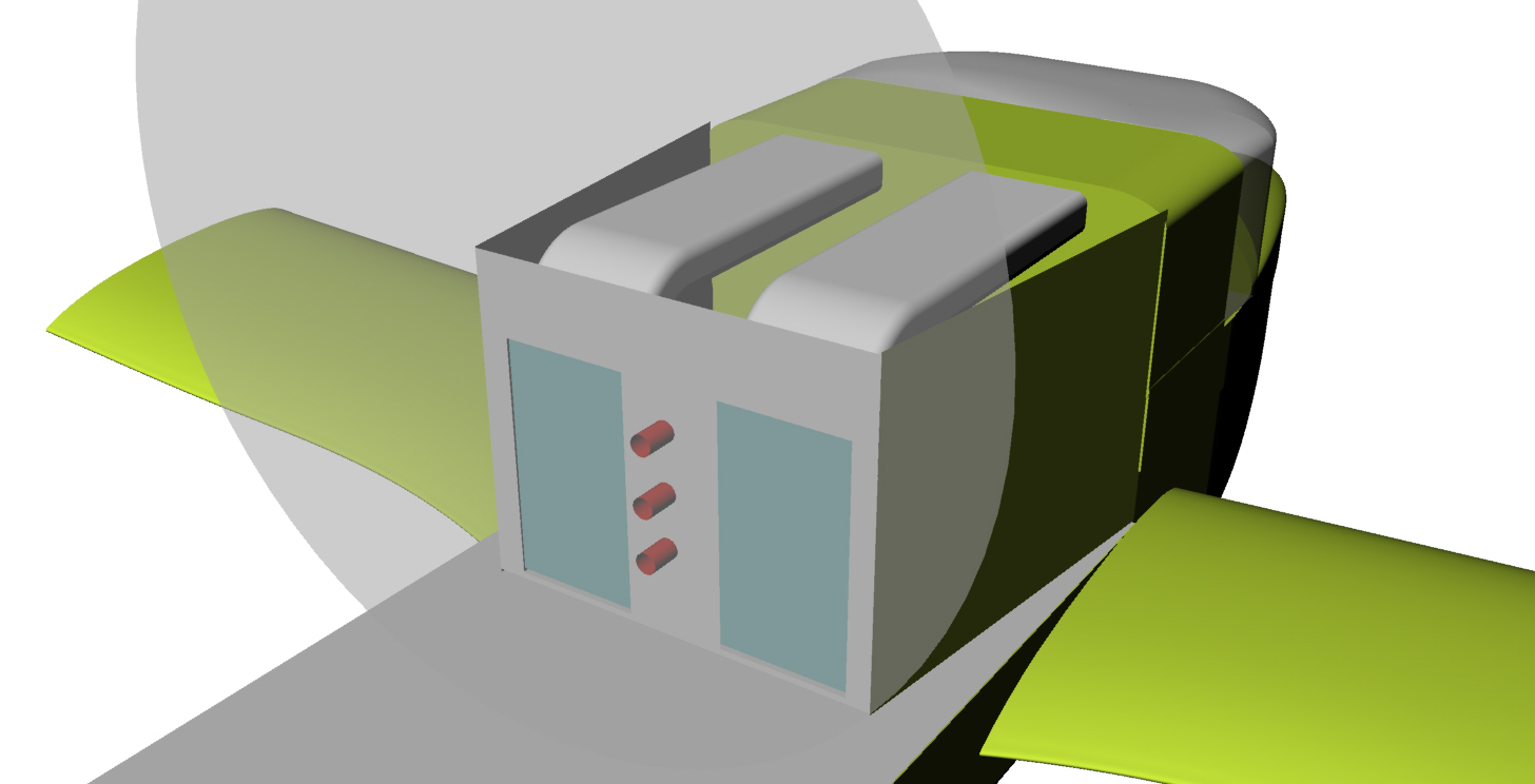
I adjusted the dimensions here and there and had another idea. I came
up with a new diffuser that would handle three heat exchangers in box
formation.
The rads are 20 by 12. You might find them in a small Honda. The top
rad can be the oil cooler. The water rads are merely in parallel.
Parallel is better in theory but you might have to adjust the flow in
each rad to equalize the inlet temperature..
They are recessed into the cabin top with water pipes coming out
under the spar.
I have another idea to get the air to stick to the pylon sides. A
page out of the SR71 design book :-) More about that later.
Paul Lamar
I'm always intrigued by your ideas!
In the GG, the upper wing leading edge is a major structural element
(also part of the wet wing), so I doubt it could be safely or
practically modified as drawn. However, a pair of smaller oil coolers
might fit on the sides without cutting into the wing, with the larger
water cooler on top, extending back over the engine. I have seen some
motorcycle radiators that are curved, which might offer some advantages
to flat radiators. Most don't advertise their dimensions.
Looking forward to seeing what you come up with regarding the pylon
airflow. I'll look for some pics for turning vanes.
Scott Gettings
One third oil cooling two third water cooling :-)
Turning vanes in general don't help much. They have skin friction drag.
Well one could put the whole cooling system underneath the engine.
I'll see what that looks like.
Here it is. This is seven degrees. Could be more moving the rads closer
together.
Peter, TTC hop on Thursday or Friday. Then it is trucked to Cal City.
Paul Lamar
The Rotary Engine free News Letter. Powered by Linux. If you want off
the list PLEASE let me know and I will remove you. ACRE NL web
site.
http://www.rotaryeng.net You Tube
http://tinyurl.com/beqqxas
Copyright 1998-2016 All world wide rights reserved.