What do you think about mounting the rads in the back panel?
This will help the drag problem as it is hard to generate
significant pressure on a panel that is highly porous. At the same
time one is increasing the cooling air flow through the cores.
I went to the Chev dealer and checked out the rad cores for the 98
HP cheap Chinese Chev Spark. At least I think it is assembled in
China at under $14,000 :-) The parts made for most cars are made in
China.
They were 12 to 14 inches high by 22 to 24 inches wide. Very thin of
course. Modern heat exchangers.
I think you will find it difficult to get smaller rads from recent
cars. Apparently all the automotive cooling engineers read my book
:-) The Neon rad was the pioneer I think.
Paul Lamar
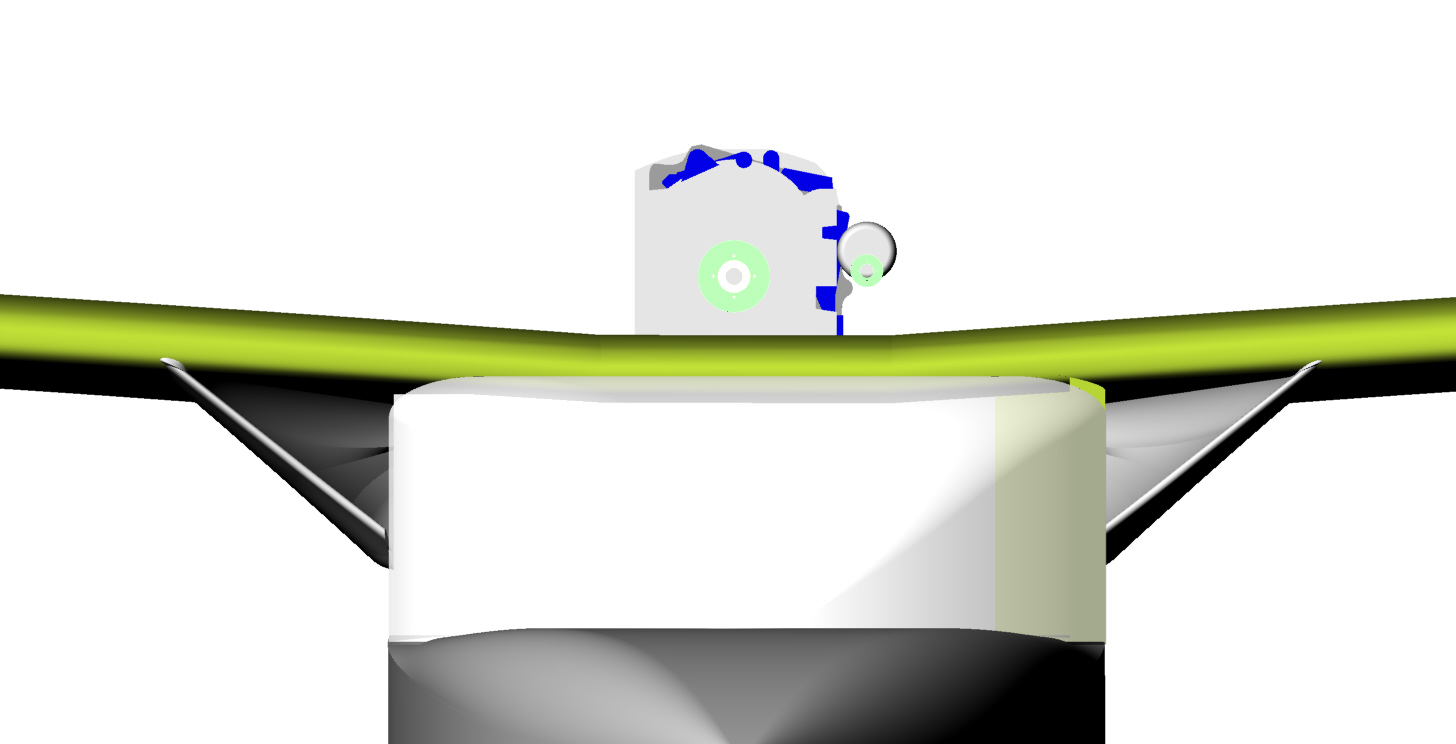
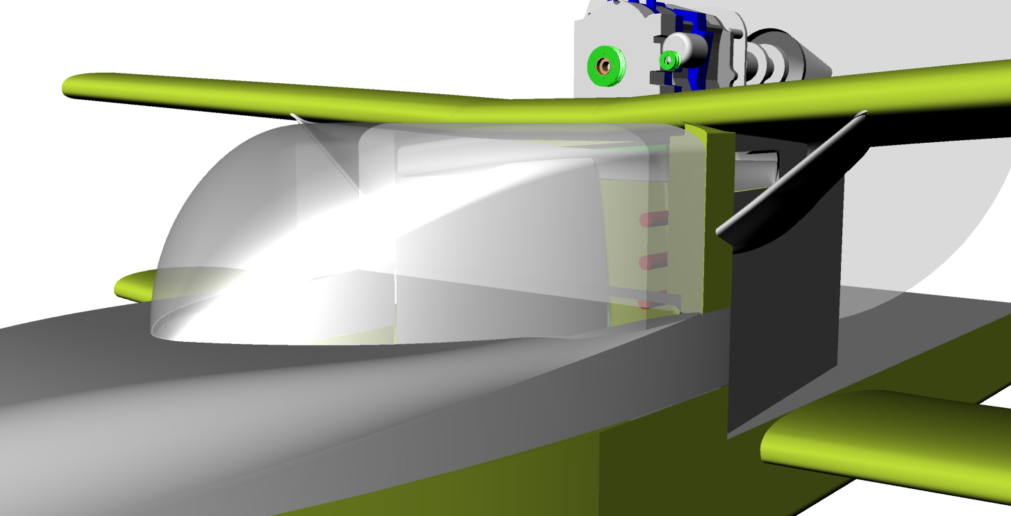
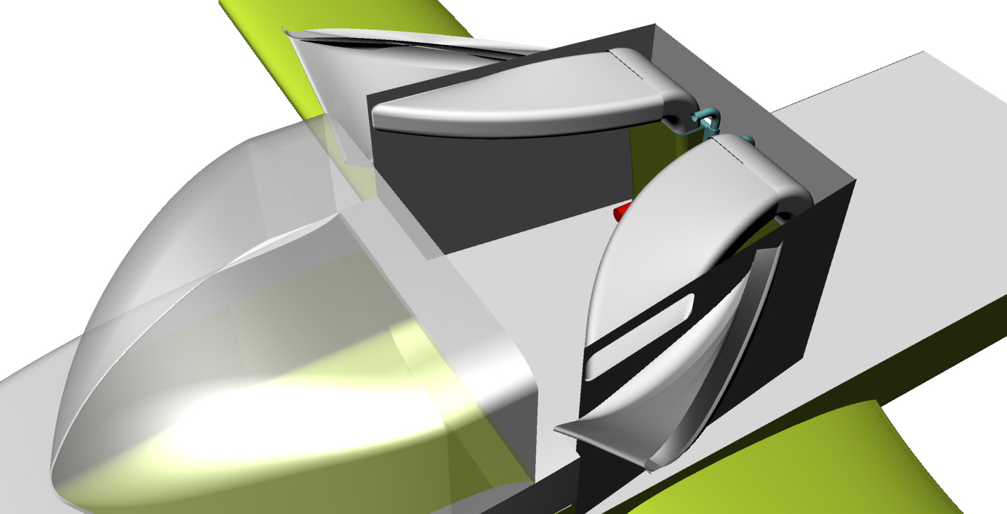
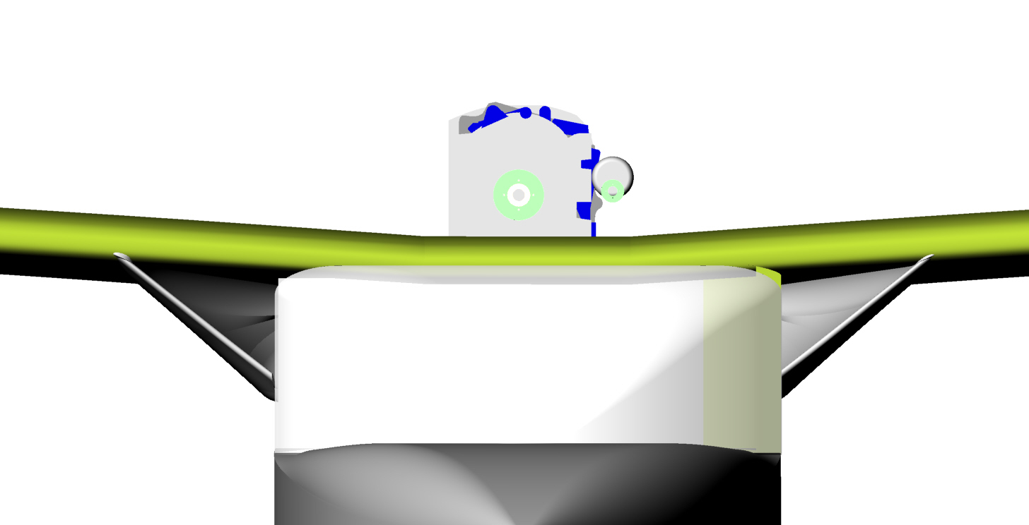
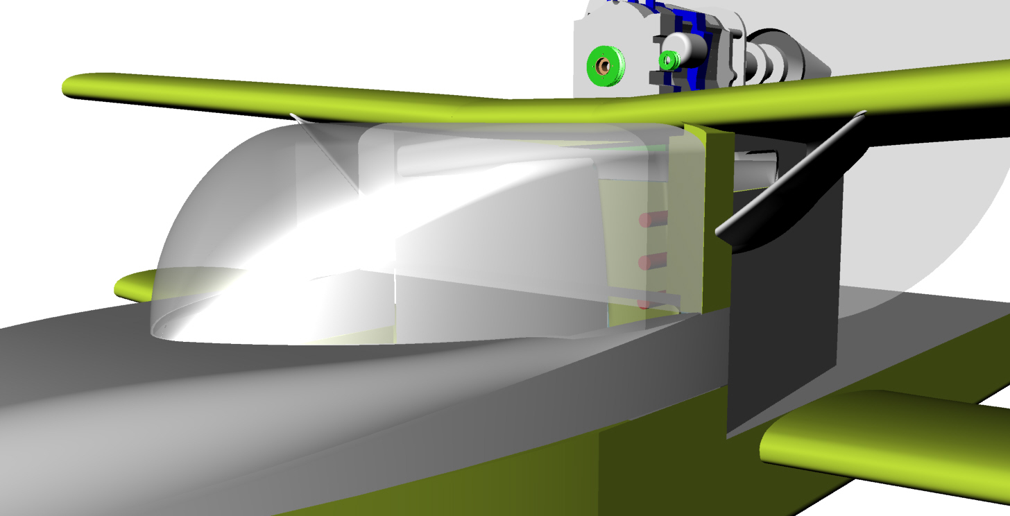
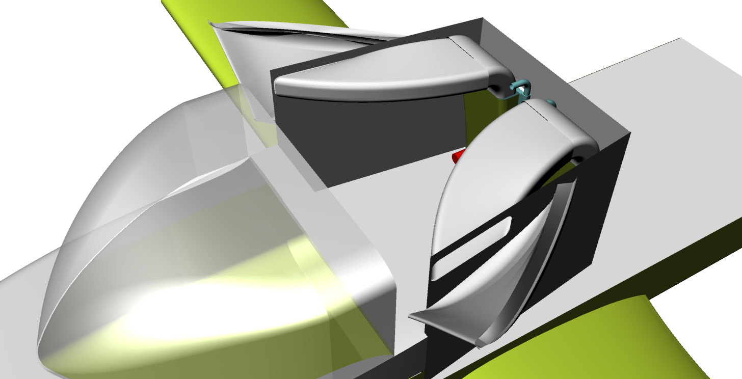
Hey Paul. I did more measurements and pictures. I mocked up a
14x26" radiator, and placed it in several positions. Obviously I
could not put this in the potential Kamm flat area without cutting
off the pylon tip.
As the pix show, it isn't feasible to bring a volume of air from the
front of the cowling down under the engine, nor have both the
exhaust and cooling underneath. The support bridge takes up a lot
of space. And the engine is pretty tight in the wing cutout.
However, the air might be able to come in from the sides. If I cut
off the pylon tip a couple of inches after the bridge (supports the
rear engine mounts), the pylon would then have a flat area about 13"
wide, and would be from 12" to 18" from the prop.
Adding new pylon walls at about 7-10 degrees would give a flat Kamm
area for radiators of about 3 feet in total width at the aft end.
I'm thinking the new walls might serve as ducts to bring air from the
sides to one or two radiators in the rear, flat area about 2-3"
behind the bridge. Side ducts might need to be far enough forward
that they obscure the rear windows -- not a critical issue. For the
ducts, 15% of 300 sq in would be 45 sq" of duct on each side that
would need to out in the airstream. Maybe 3"x15" or 2" X 23"? This
would seem to block the airflow around the bottom 1/2 of the prop,
but would allow for a smaller cowling that would disturb the upper
airflow less.
It would be nice to have a virtual wind tunnel to study the multiple
factors in play!
Scott Gettings
I think trying to bring the air in from the sides would aggravate
the separation of flow now causing a problem for drag and the prop.
The exhaust pipe can be insulated as well as the ducts and scoops
bringing the air to the rad cores.
The ducts and scoops can go under the wing spar and forward of the
leading edge. No problem. Gives you room for a stock oil cooler up
top.
Putting the rad on top will add to the frontal area and add drag.
The scoops can be faired in nicely without adding frontal area. There
is room to add the side suction feature and bring the sides into
about 12 degrees.
I think it is cool looking. Looks like a bug :-)
Paul Lamar
Scott,
what do you think about mounting the rads in the back panel?
This will help the drag problem as it is hard to generate
significant pressure on a panel that is highly porous. At the same
time one is increasing the cooling air flow through the cores.
I went to the Chev dealer and checked out the rad cores for the 98
HP cheap Chinese Chev Spark. At least I think it is assembled in
China at under $14,000 :-) The parts made for most cars are made in
China.
They were 12 to 14 inches high by 22 to 24 inches wide. Very thin of
course. Modern heat exchangers.
I think you will find it difficult to get smaller rads from recent
cars. Apparently all the automotive cooling engineers read my book
:-) The Neon rad was the pioneer I think.
Paul Lamar
Very cool ideas!
Unfortunate there is no structure through which to pass the ducts
on top in front of the wing leading edge. The movable canopy butts
against this major structure. I can't duct through the wing because
these areas are part of the fuel tanks and sumps that were internally
sealed. :-(
If side intakes would not be practical, what about an "armpit" intake
in the high pressure area on each side with about 50 sq inches of
intake area?
Scott Gettings
How about just slotting the canopy about 3 inches deep?
The arm pit scoops might work flush with the upper wing leading edge.
The area of each one should be about 90 square inches so that makes
them 13 inches wide by 13 inches high.. Taper them all the way back
to the trailing edge of the upper wing.
The side scoops shown will be in the boundary layer.
How far back is the lower wing from the upper wing?
Paul Lamar,
Well, it might be possible to build a permanent duct into the upper
canopy, that closed onto a fixed duct under the upper wing. The fuel
sumps, etc. would have to be reworked as they are all in this area.
Do you mean 90 sq inches total (90 is 15% of 600) intake duct mouth? 45
on each side, correct?
Side version: The picture shows a radiator mockup sitting where it
might fit inside the aft part of a new pylon wall of 7-10 degrees, with
the ducting formed by the old pylon and the new wall. The radiator
would be aft, not at the location of the intake. The Kamm flat area
would be wide enough to handle one wide or two narrow radiators. I was
thinking of thin, vertical ducts (maybe 2.5x18?) that just stuck out
past the boundary layer. But these could be in the armpit as well.
An upper armpit duct could start at the leading edge. The lower wing LE
is about 6" behind the upper wing. The top of the lower wing might
support a duct as well.
Question: regarding the 7 degree guideline, is there a distance over
which this angle can recur without airflow separation? The reason I ask
is the GG pylon quickly curves into about 27 degrees, then remains
flat. Does this mean if we got the air to make the 27 degrees somehow,
then it would remain attached? I think this was the original intent of
the VGs.
Too bad we can't practically enclose a radiator inside of vertical
turning vanes, which might solve two problems at once :-). (Yes I
know the airflow would mainly just run around such a device)
Scott Gettings
Yes that is probably right. A bit smaller than the ones shown.
It will take some artful sculpting of Styrofoam cores to get good ducts
with the arm pit scoops.
That would cool with proper diffuser but it adds a lot to the drag.
I think we discussed this configuration years ago.
I think your best bet is to incorporate the scoops into the canopy. No
addition to the frontal area. Lower the seats if necessary. You can make
some of it out of Plexiglas.
It is a matter of how much air you can get to make the turn. The suction
duct
would not be 100% effective. Hopefully it would be measurably.
However it is quite an R&D project and the airplane would have
to be flying. If I am lucky I can interest some of my friends that have CFD,
This is an automotive probable as well. You see more and more cars with
Kamm rear ends. You see trucks with folding back panels. More than
seven degrees.
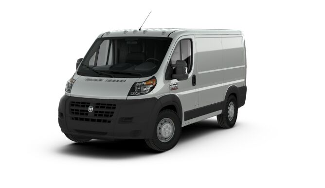
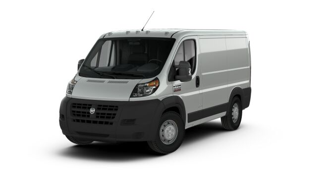
Come to think of it I could use my Dodge RAM Cargo Van
It has a computer that reads out instant MPG.
I would need some help fabing the necessary test parts.
My plate is full with the TTC and other projects.
Paul Lamar
The Rotary Engine free News Letter. Powered by Linux. If you want off
the list PLEASE let me know and I will remove you. ACRE NL web
site.
http://www.rotaryeng.net You Tube
http://tinyurl.com/beqqxas
Copyright 1998-2016 All world wide rights reserved.