Essentially the planet carrier becomes part of the prop shaft doing
two jobs. There are only two ball bearings in the entire PSRU. The
forward ball bearing takes the prop thrust.
It is only 7 inches long which is half the length of Tracy's redrive.
Don't get too excited about the weight as that Allison planet is
heavy being designed for over the road tractor trailer 450 HP diesels
towing 50,000 pounds..
The Allison planet and ring gear, sun gear, input shaft is 26.7
pounds alone.
The $30,000 Bell 47 weighs 35 pounds with out the Sonja :-) Tracy's
is 45 pounds. But could be lightened if a 2 inch hollow prop shaft is
used.
This design picks up 7 inches behind the engine for all aluminum
rotary engines only. Other wise you would have a forward CG problem.
I may not have to move the firewall back on the Glasair.
This is also much cheaper to make as no long PSRU housing is needed.
I got some of these ideas from the Bell 47.
Paul Lamar
That’s an awesome idea. I just hope the planet cage and gears are up to
resisting the gyroscopic forces from the prop. If you extended the
length of
the prop shaft another couple inches, you could add another set of bearings
to help with that. But in either event, those front bearings have to be
housed in something which can be opened for access. Probably the front
part of this housing would need to be detachable.
Gene Kahn
It is all in the steel planet cage. The gears are not involved.
The steel planet cage is bolted solidly to front and back prop
shafts via their flanges..
Actually it is better than the kludged up Bell 47 TX we have now.
Some of the bending load is taken by a small double row bearing.
Here is a 3D. Take a close look at this :-) A Sonja design.
We have no intention of doing aerobatics or stalling the air-plane.
Paul Lamar
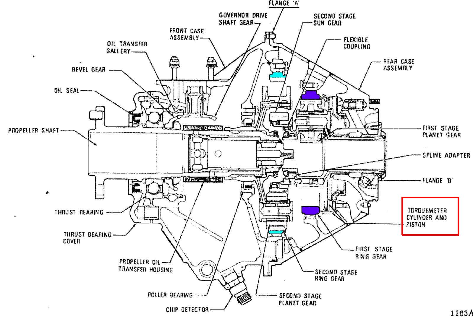
Here is the cutaway for the Aillison.
IT IS INDESCRIBABLE SIMPLE!!!!!
On the four rotor I am not going to use a flexible coupling
as the 4 rotor torque pulses are much smoother.
Less weight.
Paul Lamar
For this to work the center shaft will be turning faster than the
inboard section- are you planning a plain bearing there with an oil feed?
Will there be an inboard seal with a backplate to keep the oil in
and a seal around the shaft?
What are the ends (brown) made of. Looks much like Tracys axle shafts.
Kevin Alderman
The sun gear shaft is piloted in the prop shaft ahead of the
planetary with a small diameter drawn cub needle bearing.
There is little or no load on that bearing because planetary's are
self aligning. Max RPM for a one inch is 11,000 RPM.
It is also piloted in the e-shaft. Of course there is no relative
rotation back there. Actually the best place to take the
helical gear thrust is at the head of the engine. Back to back
needle thrust bearings will do the job. The stock 13B only has
one. Tracy failed one as did Perry Mick.
Good idea. I might be able to use a couple of forged axle shafts
for those parts.
Cut way down of course. That would save some machining. I intent
to drill
the front one out to save weight. The drill size would be determined by
the OD of the drawn cup needle pilot bearing. Roughly 1 inch.
The back seal in the gear box adapter plate will be carbon Teflon
1.5 inch diameter.
Tracy's is one inch in diameter. We may be able to use the Allison
1.43" dia. input
shaft as is. It is drilled end to end about .4 inch diameter. Total
length is 10 inches.
Paul Lamar
There is one important difference Paul. The Bell gearset is straight cut
spur gears. No side loading caused by normal operation.
Bill Jepson
It is not side loading. It is helical gear thrust.
I am well aware of that. It tends to unscrew it self. No big deal.
We dealt with that years ago. It can be measured and used to
calculate the torque. It will be handled by the thrust needle bearings
in the back prop shaft flange. This was invented about 10 or 15 years
ago by Jerry Bass. I have not heard from him in years. The beauty
of it is... it only has to do deal the difference in engine RPM and the
prop shaft RPM. In this latest 3D you can see the recess for the needle
thrust bearing. A brilliant solution. I forgot about it until just now.
BTW Needle thrust bearings are extremely sensitive to RPM.
Those little rollers are really zinging around in there :-)
The front needle thrust bearing in the 13B must deal with
the full RPM of the engine as does Tracy's solution to the problem.
How's the RV10 coming?
Paul Lamar
The Rotary Engine free News Letter. Powered by Linux. If you want off
the list PLEASE let me know and I will remove you. ACRE NL web
site.
http://www.rotaryeng.net You Tube
http://tinyurl.com/beqqxas
Copyright 1998-2016 All world wide rights reserved.