You are not going to believe this.
This makes an e-shaft cheap to manufacturer.
It takes a special right angle tool to drill the holes but that can
be done.
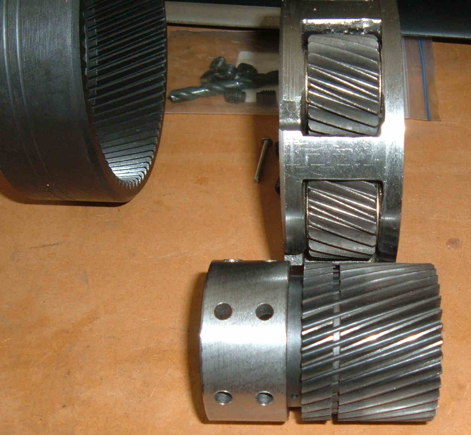
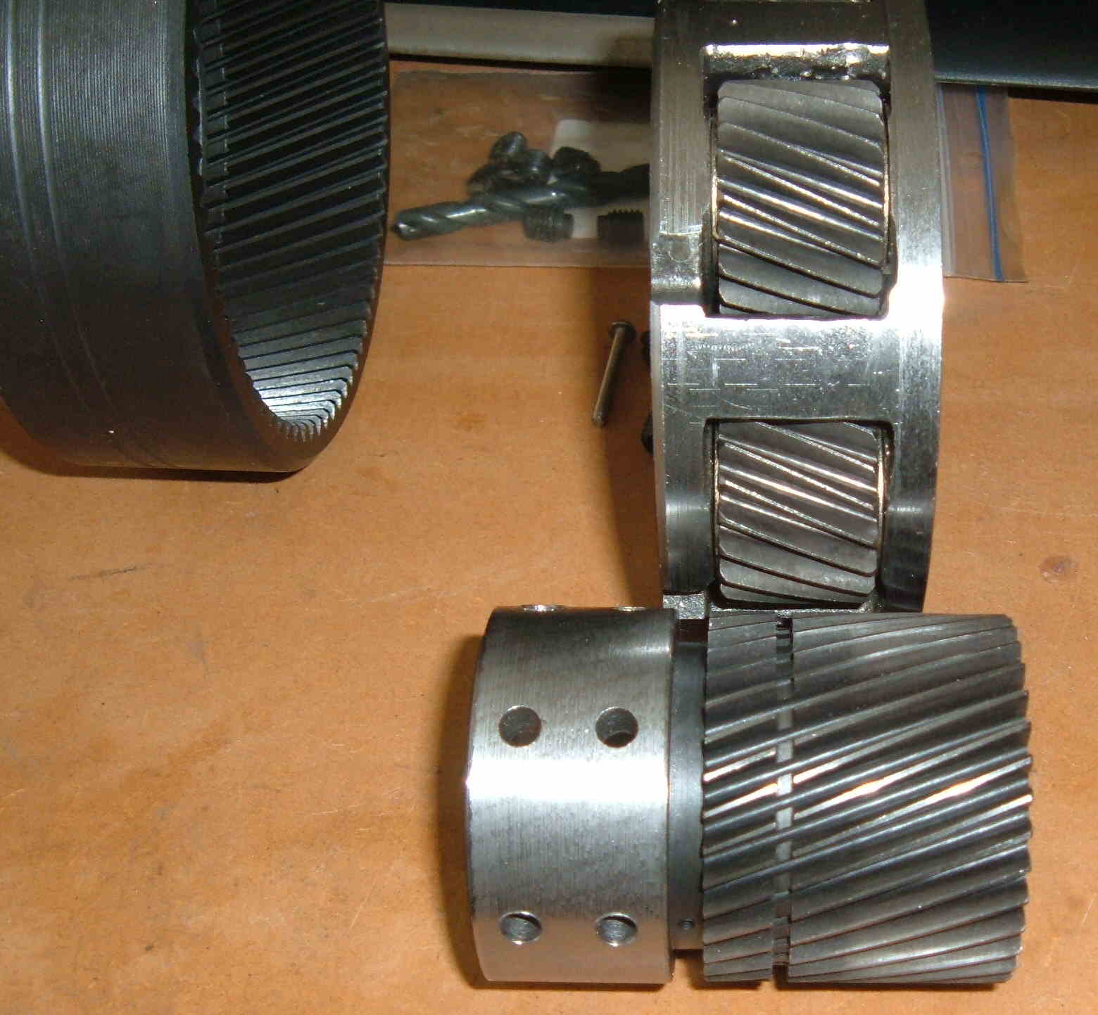
These lobes are made in quantity by an NC mill and then hardened and
ground.
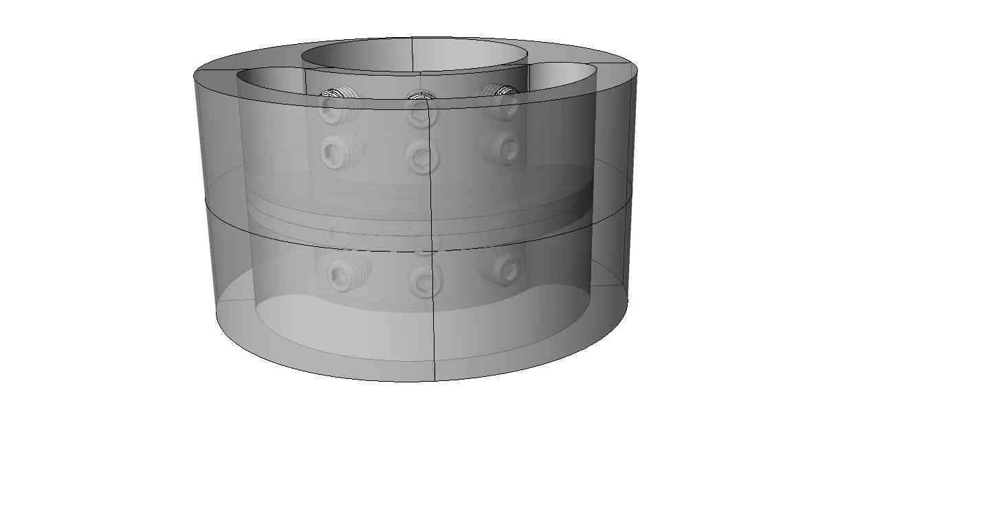
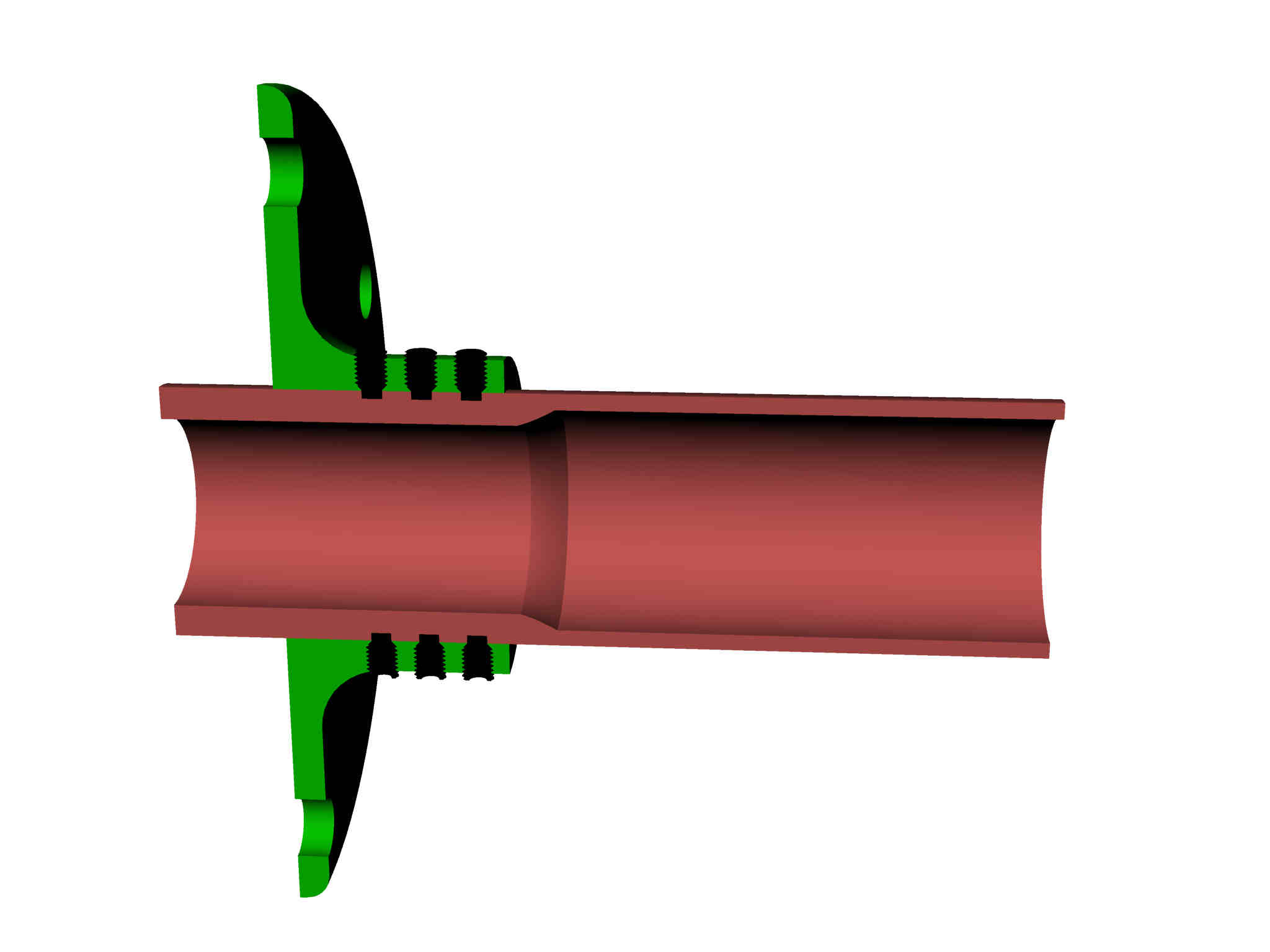
Then they are merely bolted to the e-shaft at the correct orientation
for the number of rotors. Every 90 degrees for a 4 rotor.
This assumes 200 foot pounds of torque for each rotor. A 4 rotor
turbo engine would therefor have 800 foot pounds of torque and 1218
HP at 8000 RPM. Right about what we are getting per rotor on the
Time To Climb engine.
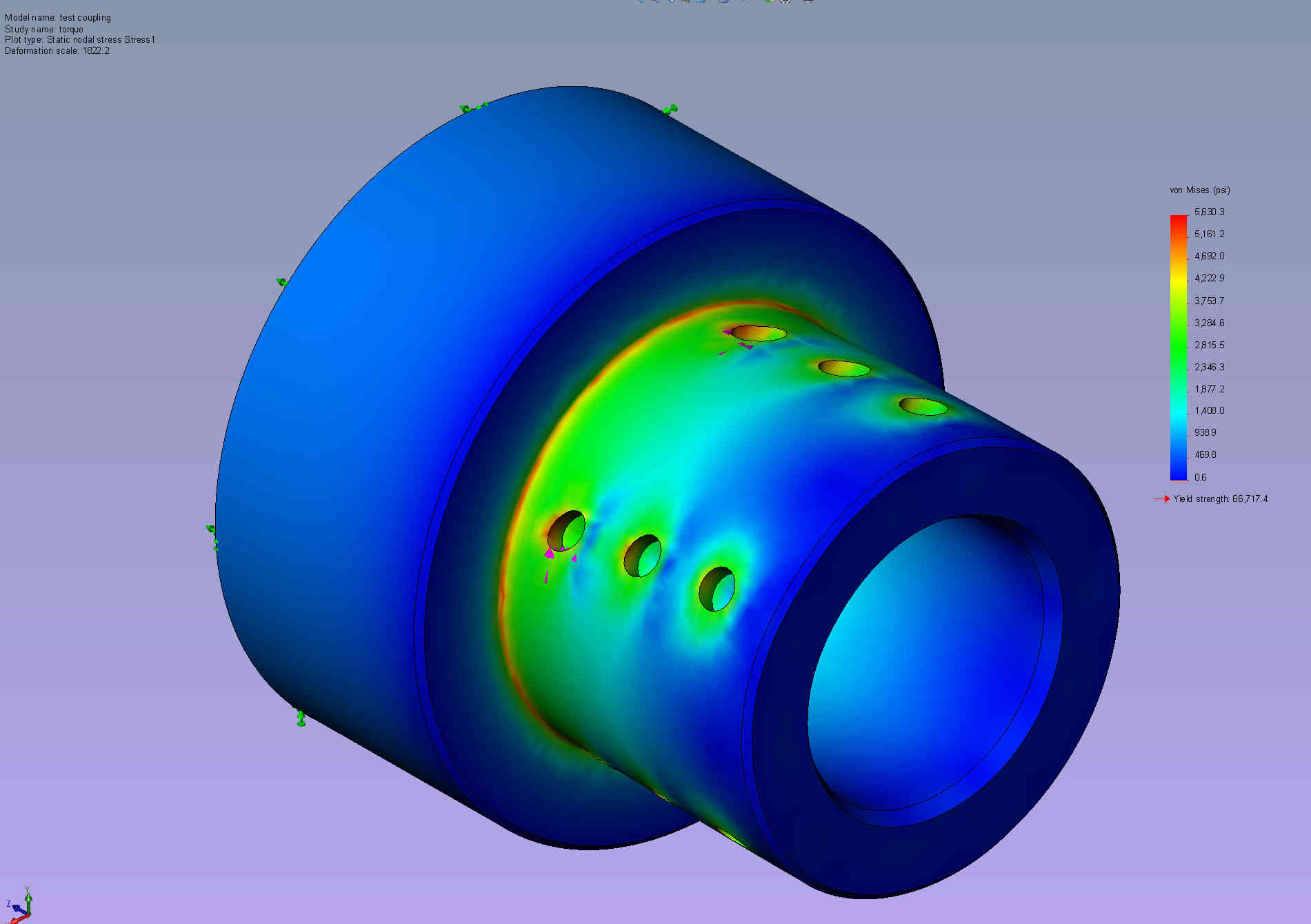
The 2400 pound number shown is the average shear load. Peak shear
load would be about twice that. Each bolt takes half of the total
shear load.
The 3/8 shoulder bolts shown are 140,000 psi. The shear area is
.110 square inches. Lets say each bolt has a shear force of 2400
pounds. That means the bolt is capably of resisting 15,400 pounds. A
huge factor of safety of six.
Each lobe is an I beam to cut weight.
I could get a patent on this but it would take years and cost a bunch
of money as well as defend it. I am donating this to the Wankel
community.
You cannot get a patent on this as I have already published it :-)
This also makes assembling a one piece e-shaft four rotor with 5
main bearings easy. No unusual main bearings devices are required
such as the Offenhouser device and method. This also cuts the cost
of the engine. You can build it up like stacking pancakes.
BTW Very few people realize the Mazda two rotor e-shaft is three
pieces. They are spin welded together. This could be spin welded as
well but some of the advantages would be lost. For example suppose
one rotor bearing was scoured from dirt in the oil. Just replace
that lobe.
Paul Lamar
Can the shaft diameter be decreased slightly? I believe the thin section of
rotor will crack during heat treat even with a small amount of material
left for ID and OD grinding.
Gary Knutson
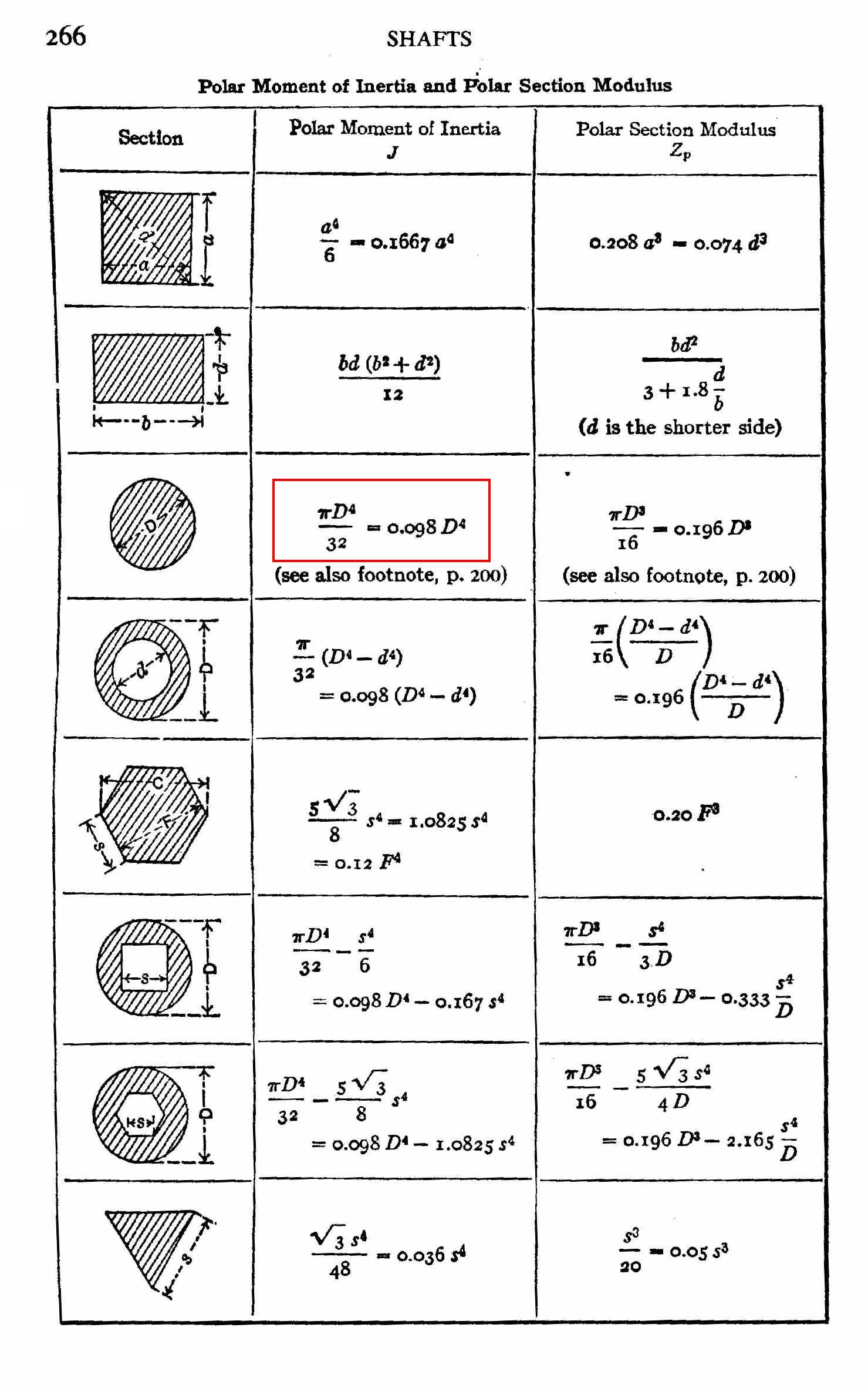
Yes I think so. However the strength is proportionally to the fourth power.
of the diameter so I will not reduce it much.
New main bearings can be machined of reduced diameter.
The rear main can be used as is.
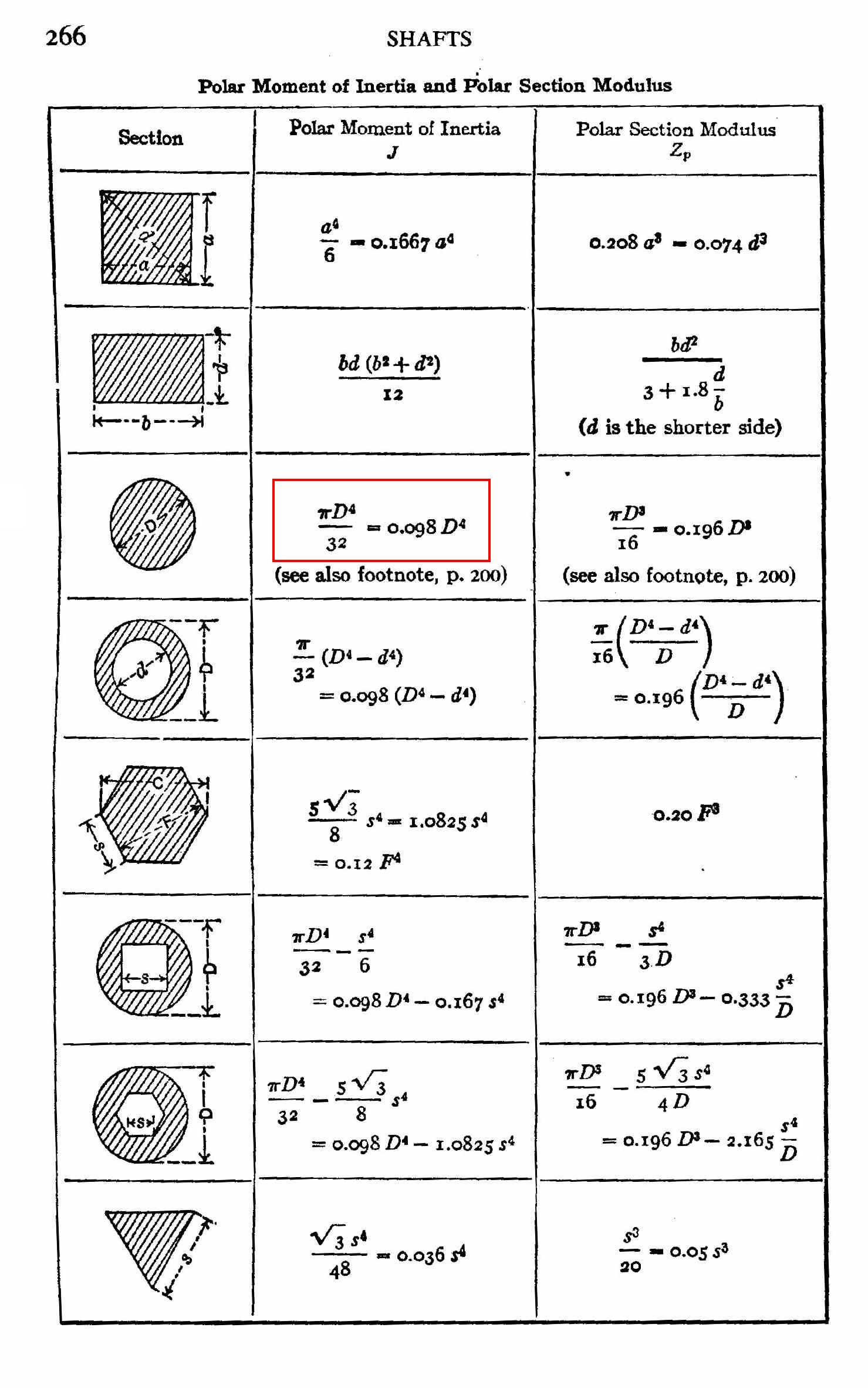
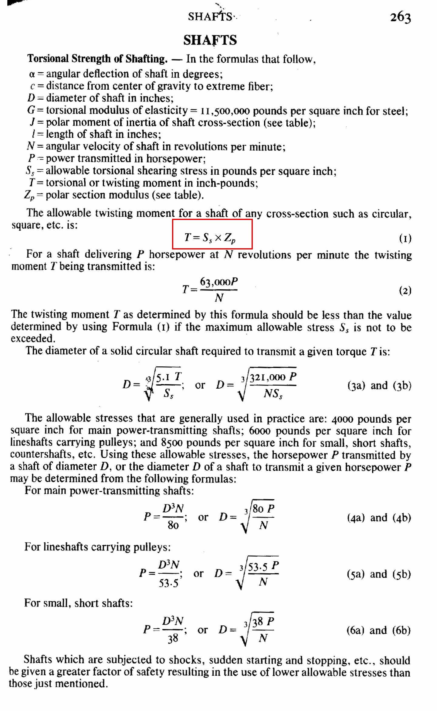
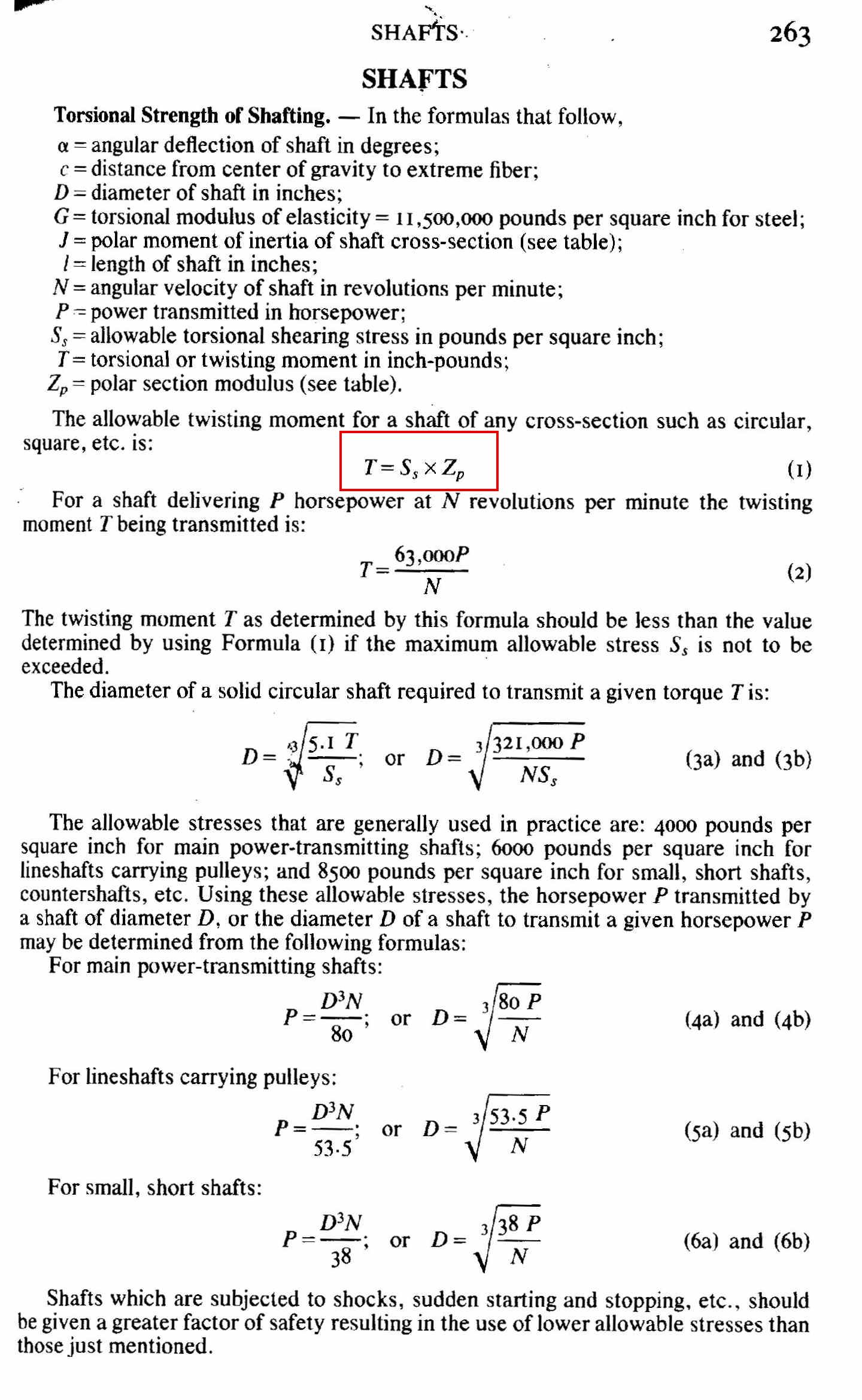
I need to make some calculations on that. Here is the math out of the
Machinery Handbook.
Unusually clear and simple because it is done in inches and not in the
silly metric system :-)
Paul Lamar
Larry Childs came up with the ultimate solution to the skinny part of the
lobes. He suggested increasing the size of the rotor bearing.
The rotor rotates at 1/3 e-shaft speed so a larger
rotor bearing would be real GOOD as the pressure in the rotor
bearing is what currently limits the RPM to 11,500.
The diameter can be increased up to 10% before it interferes with
the phasing gears.
Really GREAT idea on that.
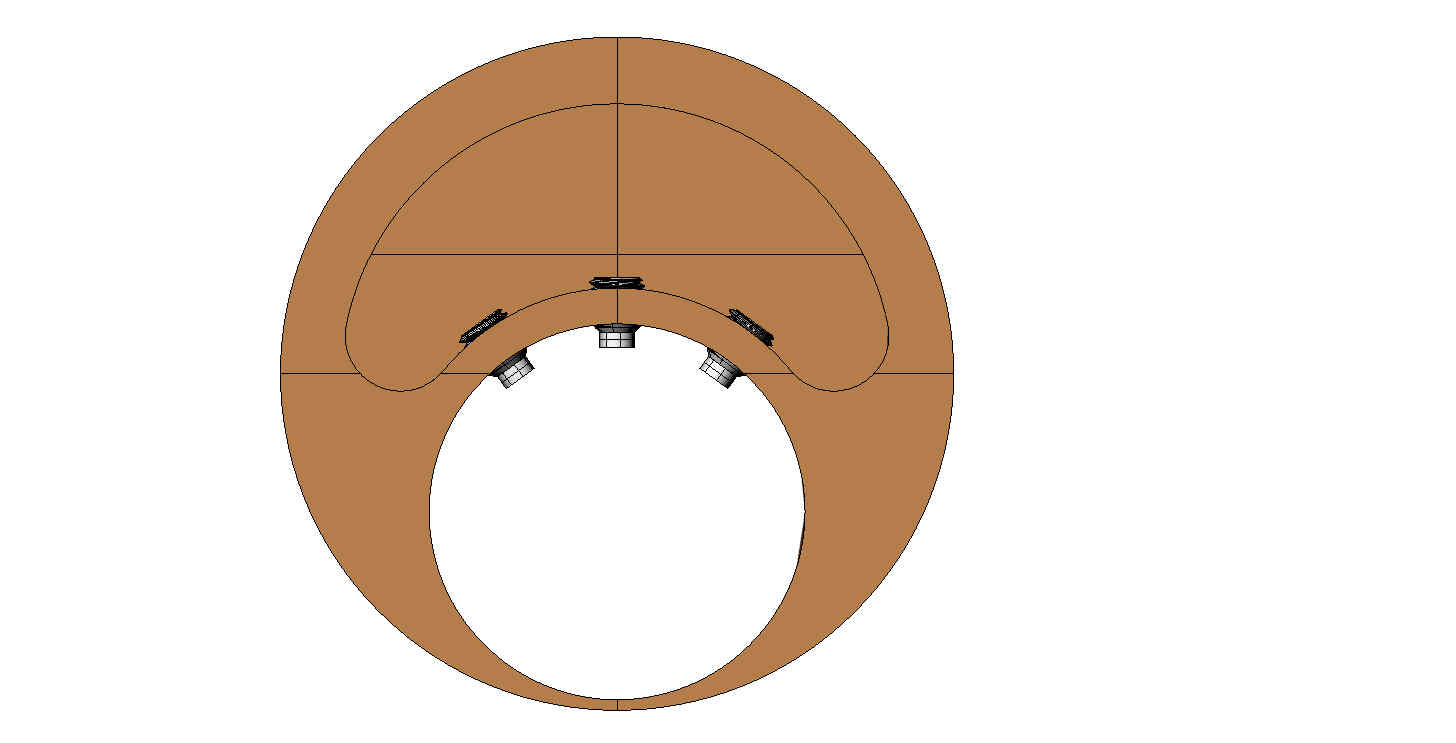
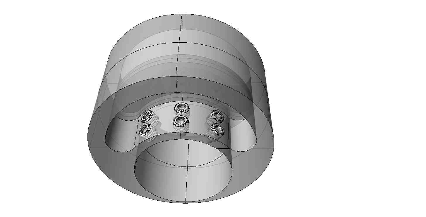
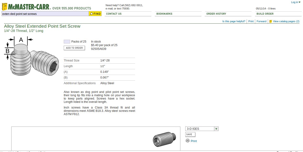
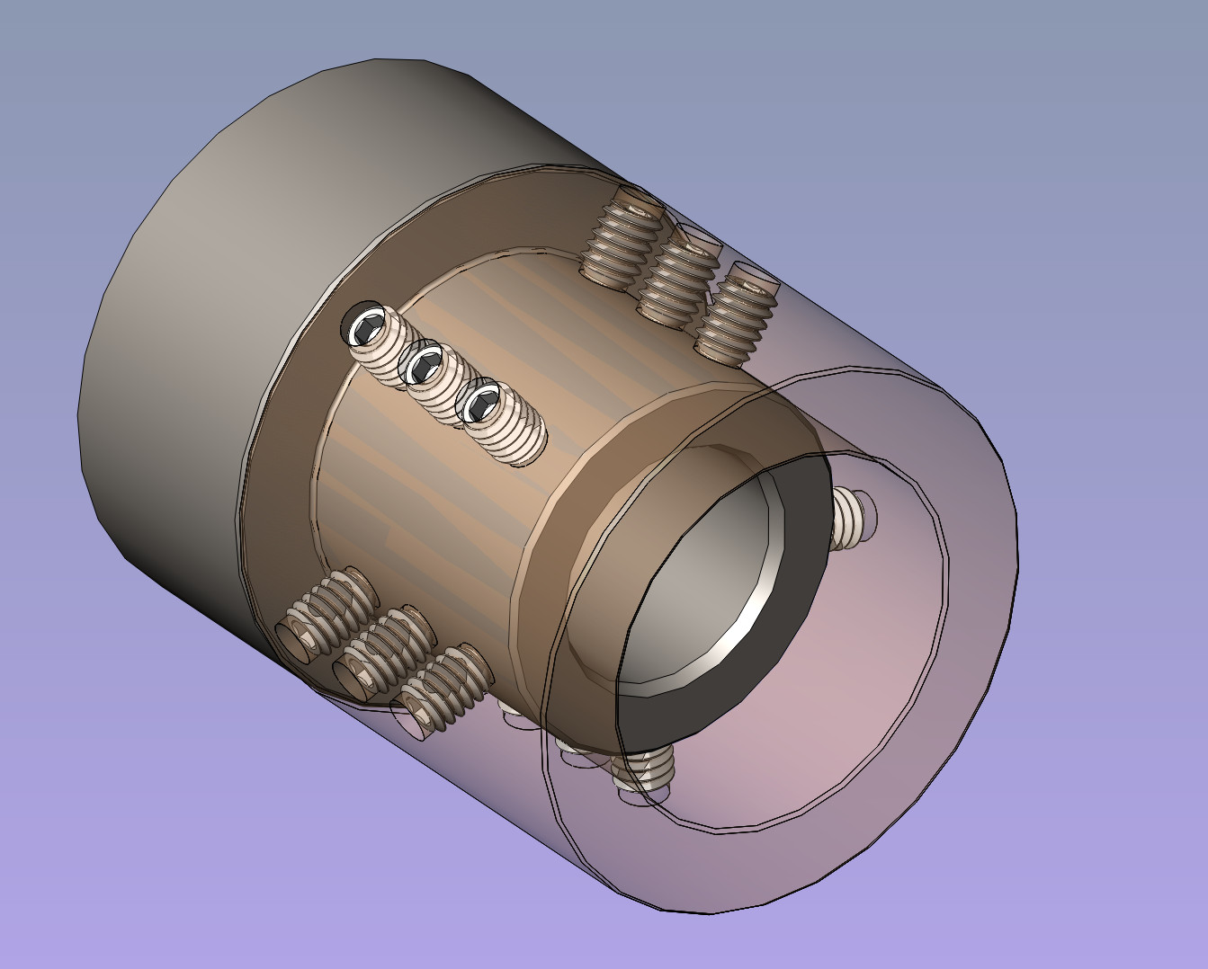
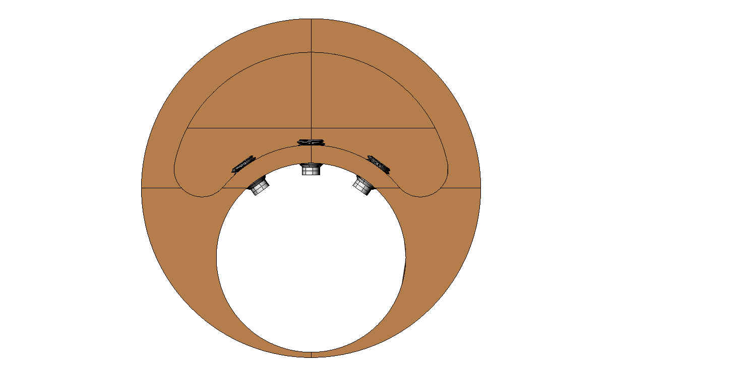
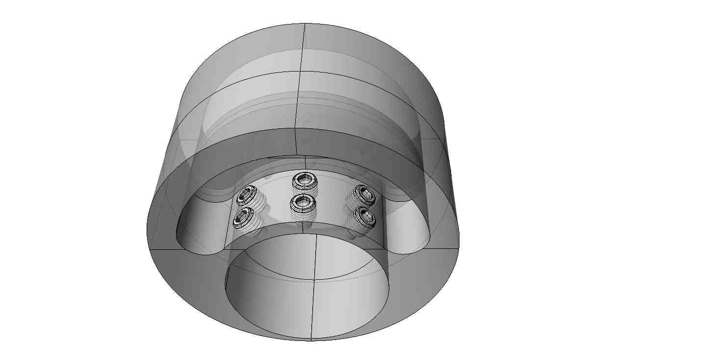
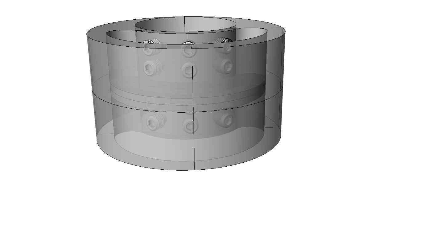
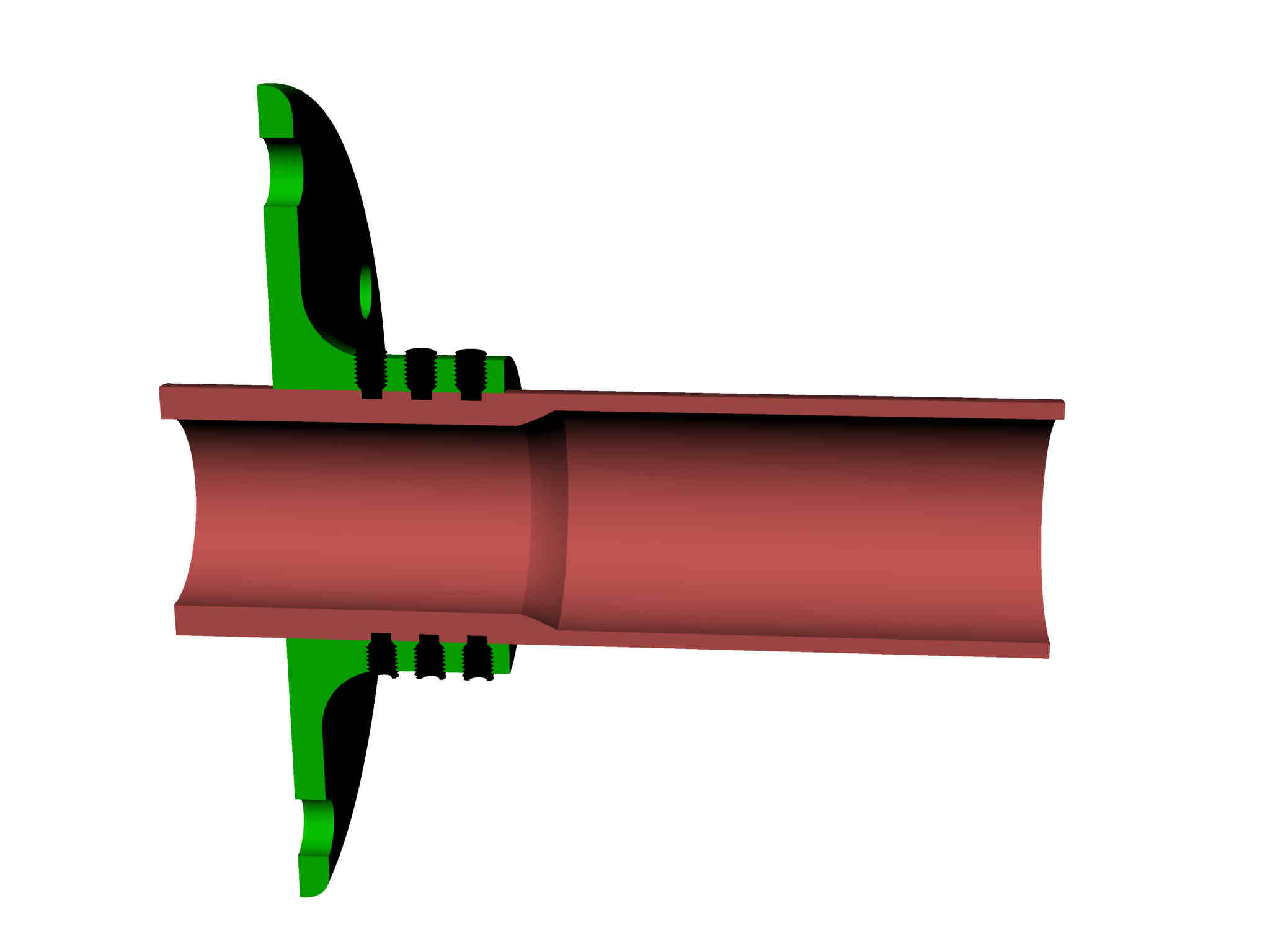
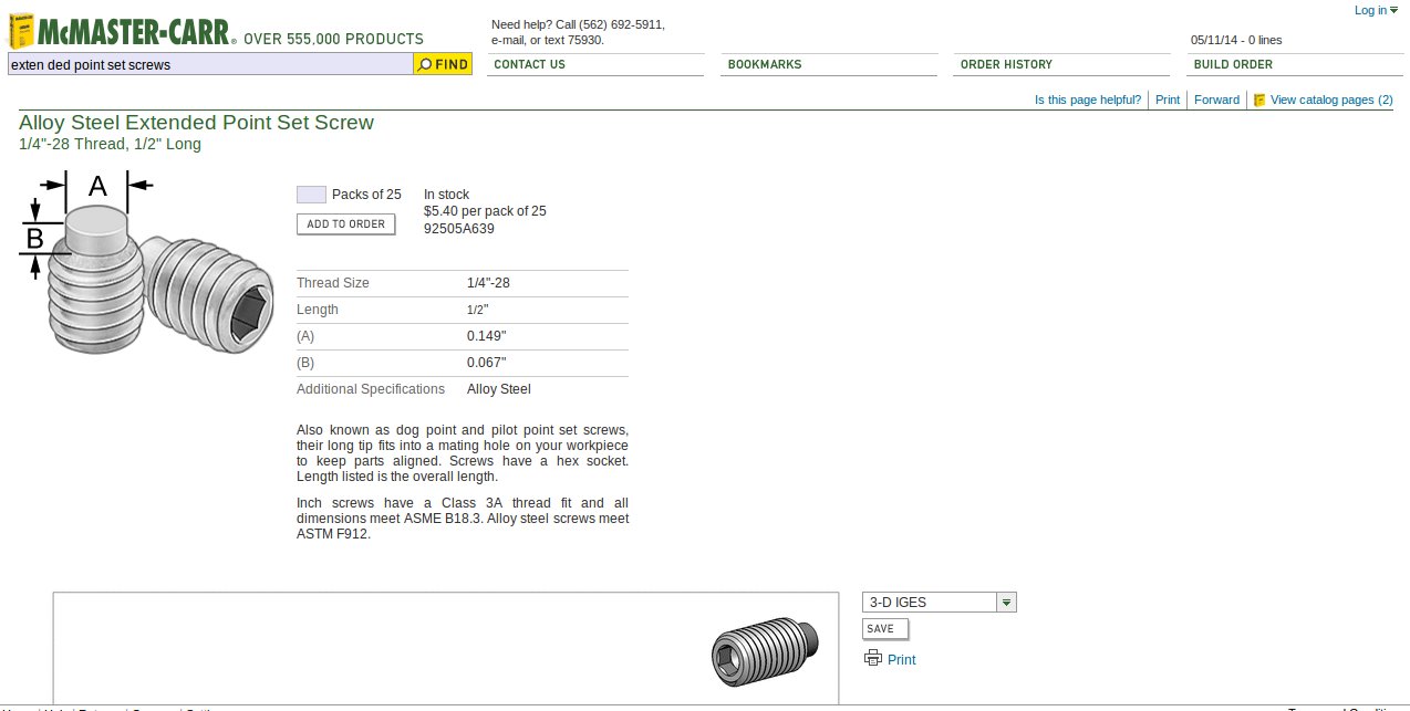
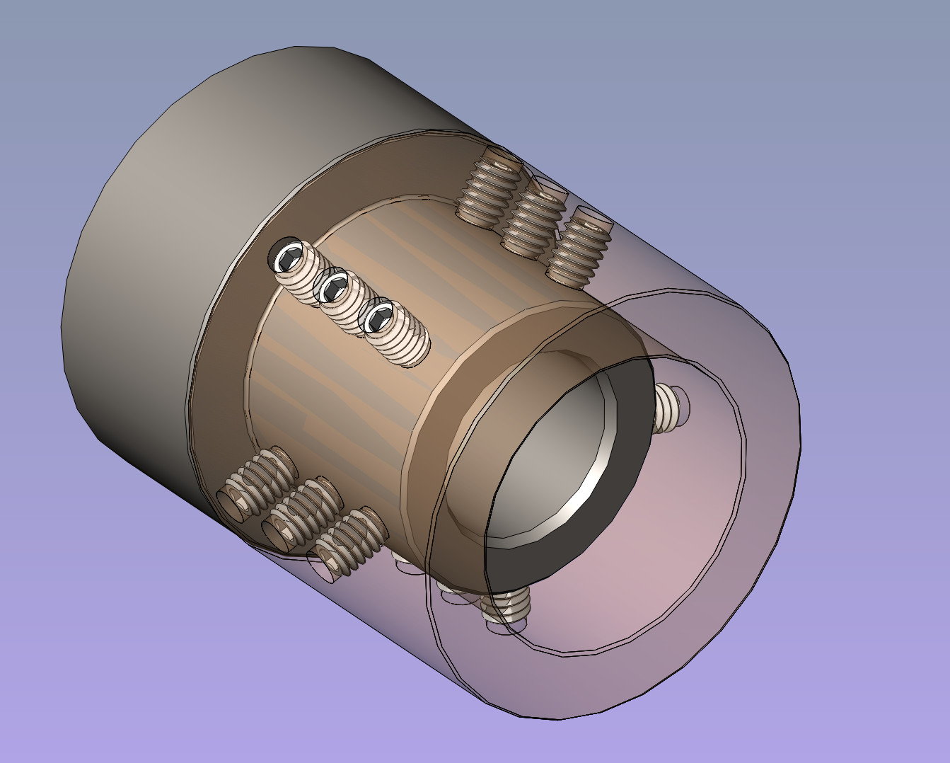
I think half a dozen Extended Point Set Screws would affect the
torsional strength of the shaft less than the bolts would.
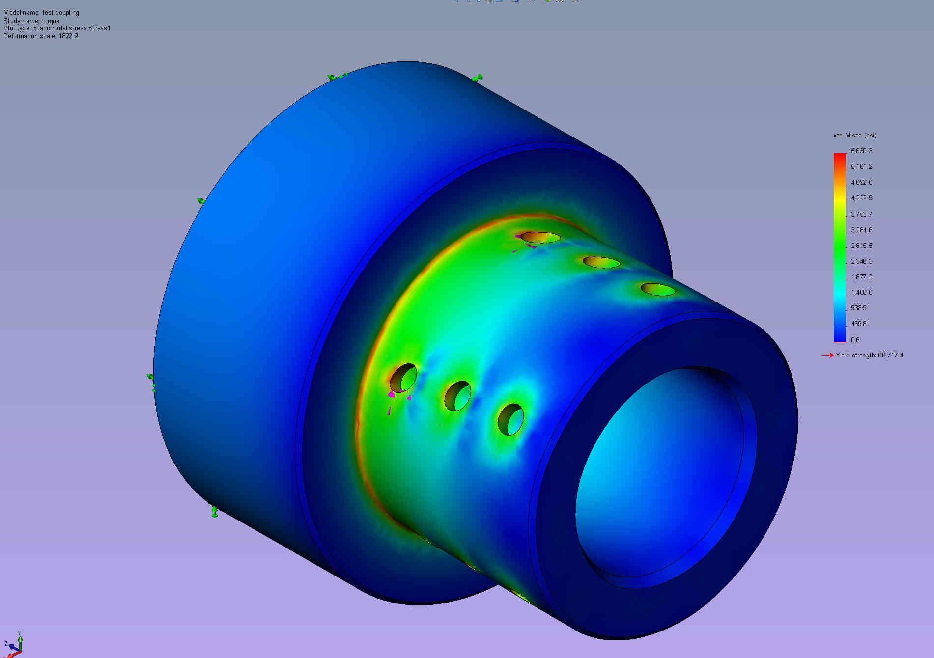
It would also distribute the stress better. A big hole in a
shaft is a stress concentration.
The combined shear area could double and reduce the stress by half.
The EPSS have wide applications not yet common so sometimes
I forget to consider them.
I like them the best as they only deal directly with the high shear
stress area
and that is the intersection of the surface of the shaft and the bore in
the lobe.
Imagine two of these engines on a drug running hydrofoil. The Coast Gard
would
have to buy fighter air craft :-)
I estimate the cost of the 1300 HP four rotor at less than $15,000.
It would weigh less than 350 pounds. Mostly off the shelf Mazda parts.
BTW This is a machine that makes crankshafts. $900,000 each :-)
https://www.youtube.com/watch?v=81UjjSH2iFw
Paul Lamar
The Rotary Engine free News Letter. Powered by Linux. If you want off
the list PLEASE let me know and I will remove you. ACRE NL web
site.
http://www.rotaryeng.net You Tube
http://tinyurl.com/beqqxas
Copyright 1998-2016 All world wide rights reserved.