Hi Guys Got back to the hangar today and thought some of you might
like an update.
After fixing some small leaks in the cooling system we proceeded to
test the cooling system. OAT was only about 20C or 68F. Engine
coolant was already approx 140F after some testing with the cowls
off.
Put the cowls back on for a stationary test - Course pitch and
2200RPM she took over 25mins for the H2O to get to 195F and Oil about
8F cooler when I shut it down. Having some pitch on the Prop makes a
big difference with the cooling.
I have no base comparison as I don’t know how other peoples setups
compare but I came away a little optimistic that she might actually
cool in the air. She is retractable so presently on the ground she
has one rather large hole in the bottom of the cowl. What happens
when that hole gets plugged is unknown, I’m hoping pressure in the
cowl drops and cooling increases, but we’ll have to wait and see.
Engine ran silky smooth on B, less so on A, so Ive got some
investigating to do.
Hoping next week to do a fine dynamic balance of the prop and maybe
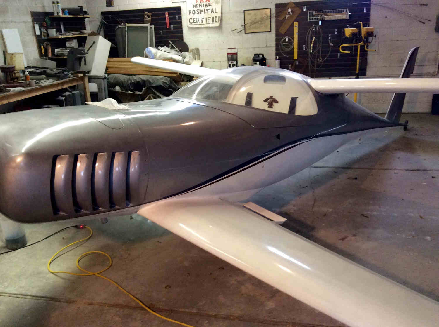
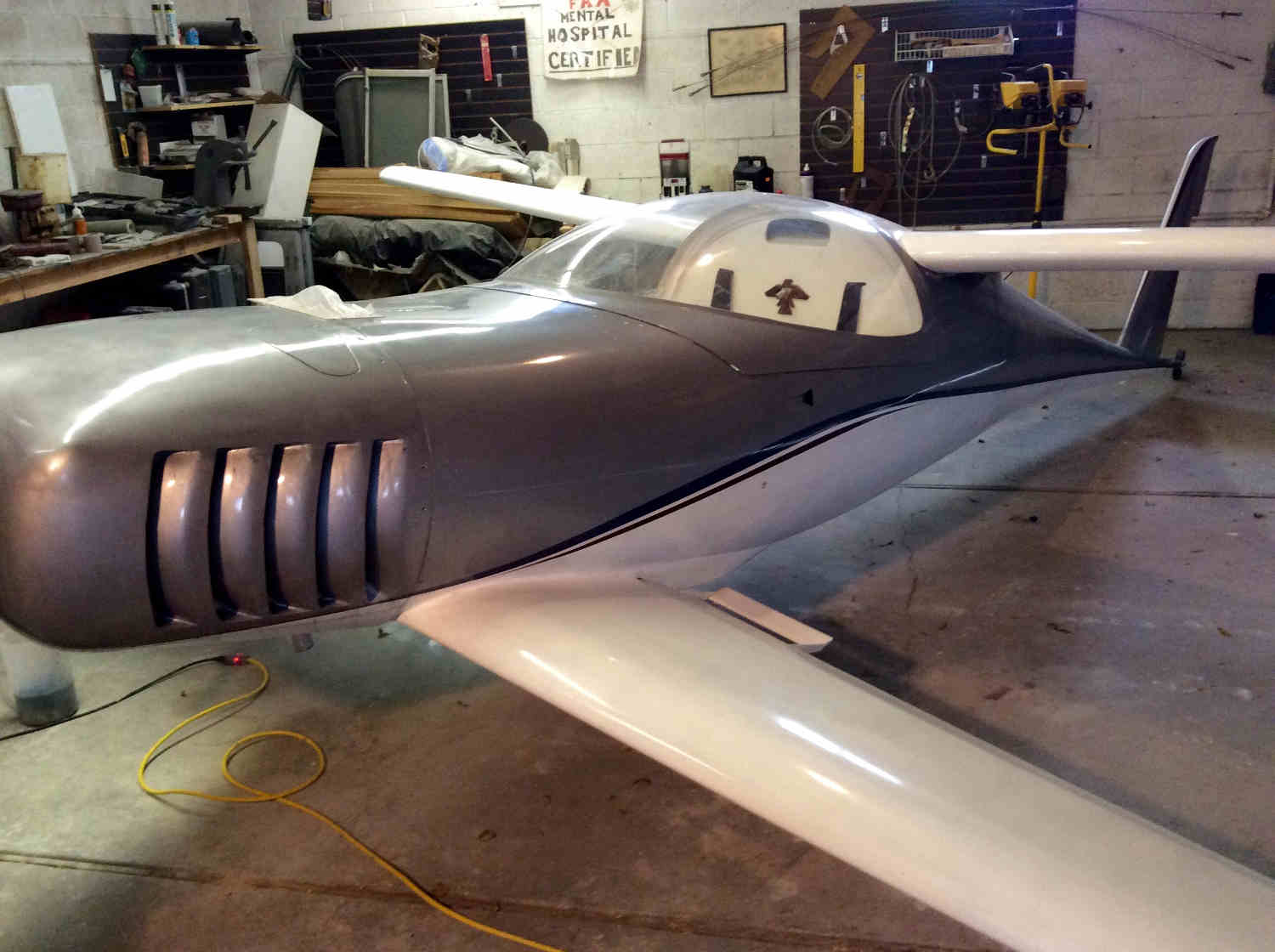
taxi her and see what that does to the cooling. I’ve attached a frame
from a movie I took today. (The prop looks pretty bent!)
Cheers Steve Izett Glasair Super II RG EC2 EM3 RD1-C
Good work Steve.
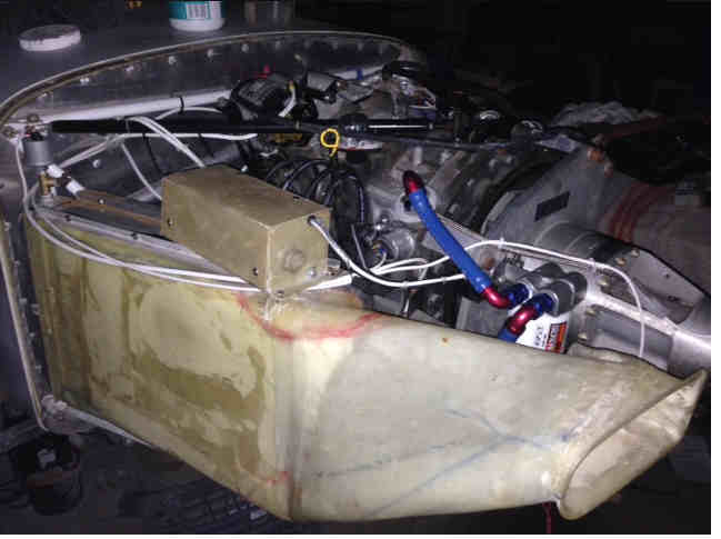
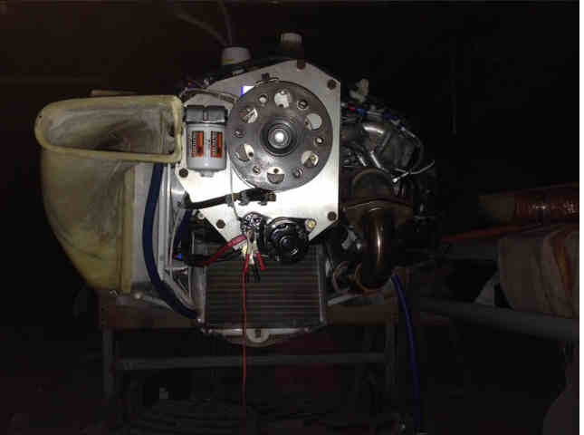
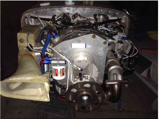
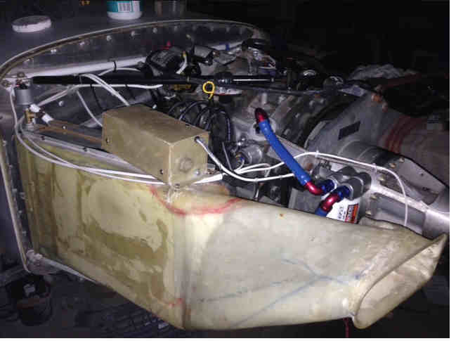
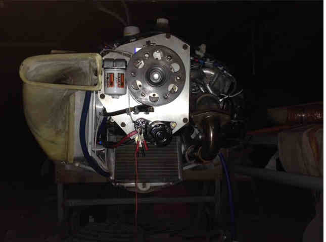
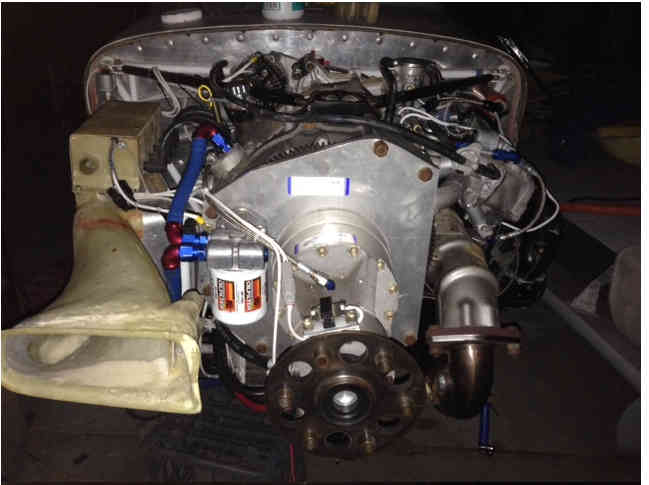
Can we have some pictures with the cowl off to see what the cooling
system looks like?
Paul Lamar
Hi Paul
Here are some photo’s
The water exchanger is 17.7 x 13 inches ~ 540 cubic inches.
Located on the cool side feb by a divergent rotating diffuser which then
feeds a wedge diffuser.
Entrance area of Right cheek from memory is approx. 18 sq inches. I
think Tracy is cooling his 20b with 5.25” round cheek - just under 22 sq
inches of inlet.
The oil exchanger is 11 x 8.75 inches (Out of an Rx7 turbo not sure
which series) ~ 193 cubic inches
Located under the sump sitting back @ ~45 deg angle fed by a divergent /
wedge diffuser.
I don’t remember the entrance area, probably around 8 sq inches.
The Left cheek is half blank at present with the other half feeding air
to a filter box behind the engine.
Exit area is a ramp either side of nose wheel home of approx 36 sq
inches total.
Left exit ramp has exhaust ejector which I’m hoping will pump air out of
the cowl lowering the pressure.
If exit area is not enough we designed the exits so we could cut and fit
cowl flaps.
I’m building a pressure data acquisition module in the next few weeks
with 5 differential inputs to probe the faces of the exchangers and cowl
pressures.
I wanted to have this ready for first flight to understand whats
happening across those exchanger faces and cowl pressures.
Cheers
Steve Izett
The engine heat radiation and under cowl temperature's including the
heat from the exhaust
are heating the core.
It needs to be turned around 180 degrees with outlets on the side of the
cowl.
Rule of thumb. Always put the diffuser between the core and any source of
heat.
Tracy did it wrong.
Sorry about this Steve.
For those building a rotary powered aircraft send me pictures of what
you propose on the cooling system before you do it.
Always do it the way it is shown in my book.
The diffuser is always between the source of any heat and the cooling core.
Steve's set up will then cool under any circumstance. With or with out
the cowl.
Paul Lamar
The Rotary Engine free News Letter. Powered by Linux. If you want
off the list PLEASE let me know and I will remove you. ACRE NL web
site.
http://www.rotaryeng.net You Tube
http://tinyurl.com/beqqxas
Copyright 1998-2016 All world wide rights reserved.