I am working on the design of the carbon fiber six inch diameter
tube spar.
The spar is the heaviest part of the aircraft structure so it pays
to make it out of expensive carbon. The skins of course can be glass
or carbon depending how much money you want to spend.
Paul Lamar
Paul, I am sure you are aware of the method that Paul McCready used
to make the carbon fiber spars for the Gossemer Albatross:
He used Aluminum irrigation tubing (~3-4" D) and laid the carbon
fiber up on the tubing, then dissolved the Aluminum out with KOH.
Bill Schertz
I was called in as an aerodynamic consultant on the one that
eventually won the Kremer prize by Jack Lambie round about 1976 or
1977. My girl friend Rhonda and I drove up to the valley to have a
look. I was surprise to see a propeller about 4 or 5 feet in diameter
made from two model airplane wings and wire braced. I suggested a
larger diameter prop not wire braced and further geared down. They
did that and went on to win the $50,000 prize :-)
I was not aware he built the spar that way. I was thinking of using
a metal or plastic tube covered with several layers of garbage bag
or other thin plastic material cut in long strips. After the epoxy
is cured the spar can be slipped off the tube. I have done that many
times on shorter composite tubes. Sometimes the strips can just be
pulled out from between the surfaces. That gives enough clearance to
remove the spar from the tube.
How's the Kiss Cruiser doing? Do you like living up there in the US
bush? :-)
Paul Lamar
Paul you can also use braided carbon fiber. You get it in a flat role
with different diameters. This way the "braided fibers" are in a more
or less 45 bias in the weave to the span of the spar. Do 2 layers
then dremel cut out of the male plug ( split the carbon pipe) to get
off the male plug. Then do several layers braided over the "first
split mold" to the different stations according to the bending
loads and specs Vacuum bag each layer as you progress and scuff
between layers to get nice finished surface between layers
Le Roux Breytenbach ZA
One needs some unidirectional fibers on top and bottom of the tube
to take the high bending stresses. These should be layered with the
thickest layers near the center of the wing.
Paul Lamar
Spar caps can use pultruded carbonfibre rods
http://www.marskeaircraft.com/carbon-rod.html
<http://www.marskeaircraft.com/carbon-rod.html>
Carbon Rod - Marske Aircraft Corporation
<http://www.marskeaircraft.com/carbon-rod.html>
www.marskeaircraft.com
Learn more about Graphlite Carbon Rod, Pricing, and how place an order
with Marske Aircraft Corp
Le Roux Breytenbach
Hi Paul,
Round tube spars are usually an inefficient use of materials for a spar!
The only bits taking the loads are the upper and lower one eights.
Why not a box spar or an I beam?
Ray Tolhurst
Aw so that is assuming the wall thickness is constant around the
circumference :-)
The I beam is hard to layup. The round tube is the cheapest male mold.
However I am leaning toward a tapered box tube sections made from .032
thick 5052 ten feet long then tig welded together to make a 20 foot long
male mold. The welded joints are then sanded.
It is hard to find 20 foot look press brakes and 20 foot long sheets
of aluminum.
If you seal the small end with a tig welded cap. The aluminum male mold
will pop out of the cured spar when water pressure is applied to the
small end.
Patent pending :-)
BTW Another reason for rectangular or square tube spar is it transmits
the torsional load from the ribs into the spar better. It is a simple
matter to layup angle reinforcement layers to do this as they are linear
and not curved. In fact one may find pultruded angles that can
be cut in short pieces..
http://dragonplate.com/ecart/categories.asp?cID=34
Check out Pitching Moment Characteristic in Von Doenhoff page 179.
Also page 214 for Fowler flaps. I am looking for a C sub L of
over 2. My C182 is fantastic in that regard.
BTW I am thinking of offering plans if you have Solid Works or
Rhino.
Paul Lamar
Paul
I do have an idea to built by using a big pvc pipe which the inside
diameter meet your requirement
Cut it in half and install over a long steel angle or steel channel to
keep it straight,
Wax it inside and lay down the carbon fiber and trim each side with a
knife before full cure,
Sand each inside edges and rejoin both sides with several carbon fiber
ribbon
By placing it with a long rod and attaching the wet ribbon who have
prewet over polyethylene plastic strip.
When in place use a special made curved roll as same radius of the
inside tube and attached to the long rod ,
Before removing the polyethylene strip to prevent the roller to stick
on pre wet ribbon,run it several time over the wet ribbon to make sure
it lay down perfectly and bubbles removed.
Let it cure and when done remove the plastic polyethylene strip over
the jointing ribbons
You will have a perfect outer diameter and strong spar to built your
wing the spar .
JEAN PRUDHOMME
Hi Paul
Have you considered fiber reinforced tubes for the spar
These are relatively cheap and light weight
I happened to have a tube in the shop 110 mm OD, 3.2 mm wall as
shown in picture It weighs 4.9 lbs for a 4 ft section or about 1.25
per linear foot
In spite of the thin wall this tube is tough and stiff (maybe not a
desirable feature but I am not an expert). I would estimate this
would easily carry a ton of side pressure mid span. Unfortunately I
don't have a strain gage or would run some tests with the engine
hoist I don't remember what I paid but it was pretty cheap maybe $25
per foot ballpark
Also, years ago I was doing some experiments while trying to make
the worlds lightest bike frame and the process I came up with is
applicable for making wing ribs. Each rib would be approx 200 grams
for a 4 ft wide rib section and strong as heck. Scales linearly. Not
sure how competitive weight-wise with foam ribs. Can you let me
know?
Is there a typical rib spacing used on light aircraft or are they
all over the map depending on specific designs
Regards,
Simon Saba
I was thinking about flaperons and decided it was a bad idea. I am sure
it takes
a lot of flight time to get the handling just right.
So I decided to copy the C182 wing planform in carbon composites.
It has known good handling as I have about 3000 hours in one.
That meant a straight wing out to the ends of the fowler flaps and
tapered from there on out.
So a rectangular carbon tube with reinforced top and bottom would be good
for the center section. I would need a tapered male mold from there on out.
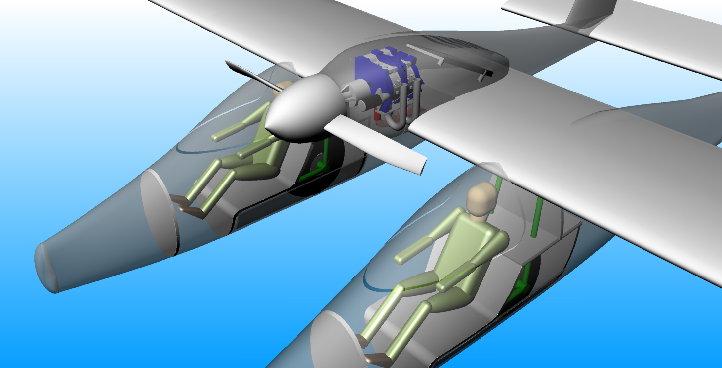
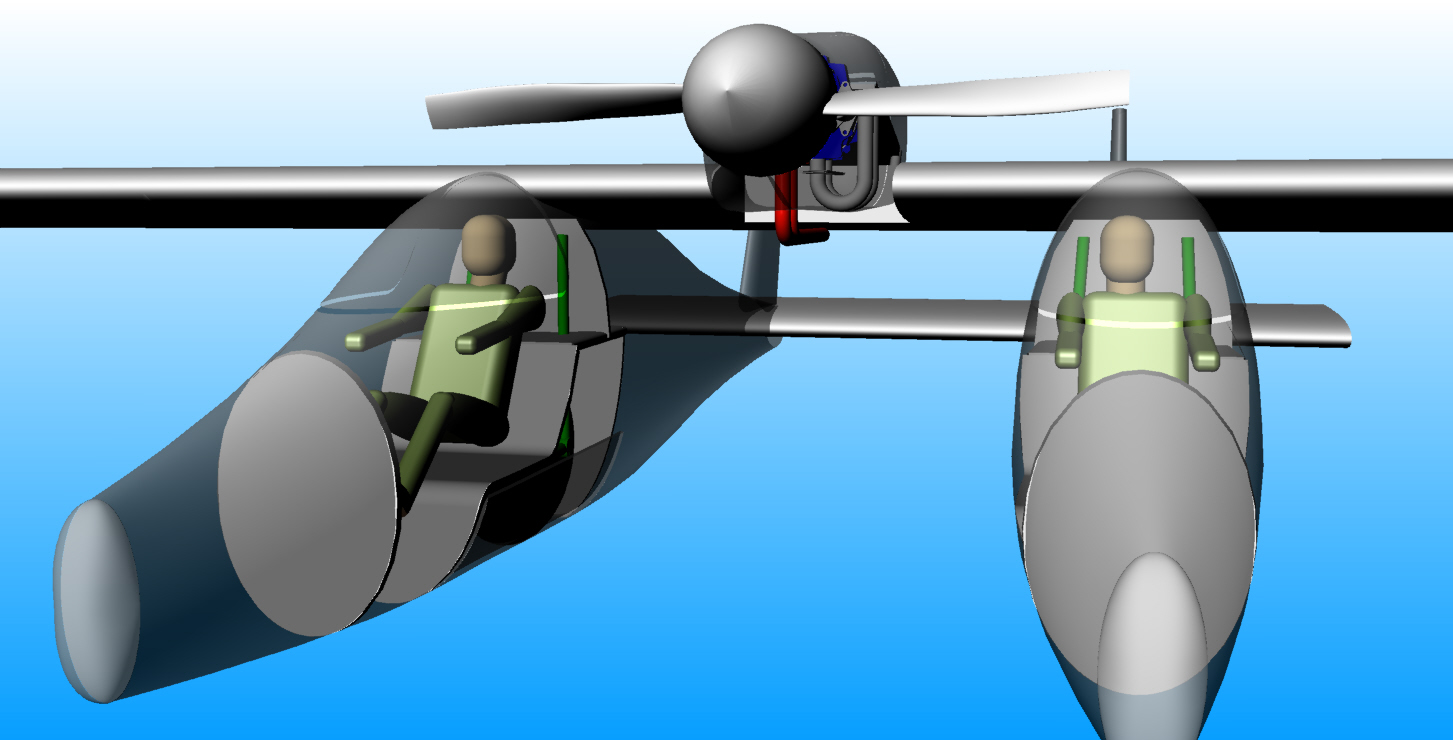
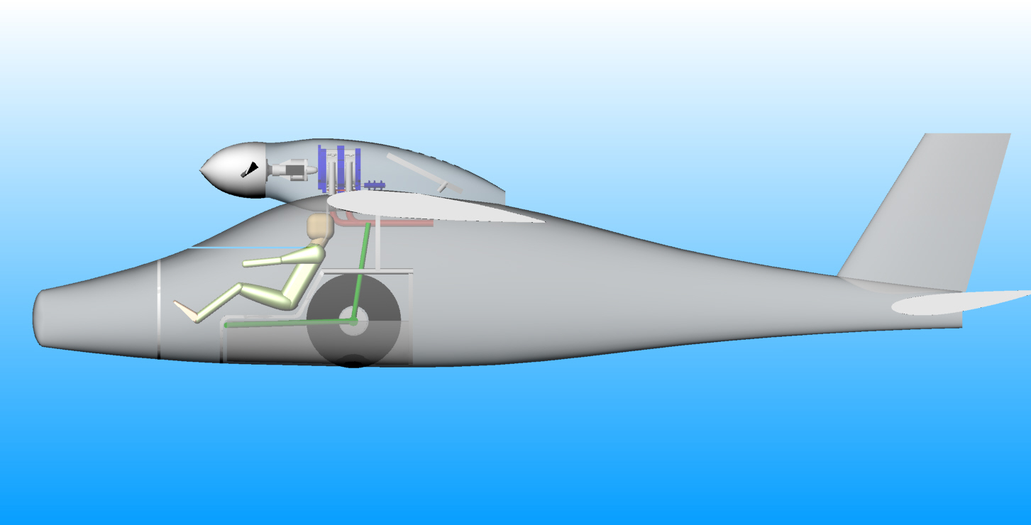
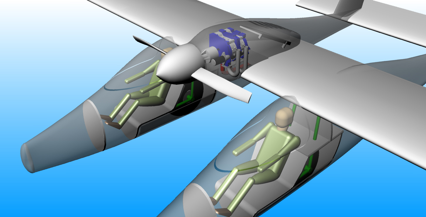
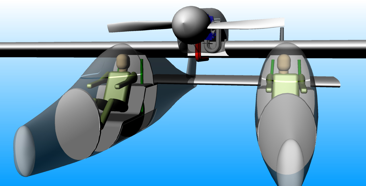
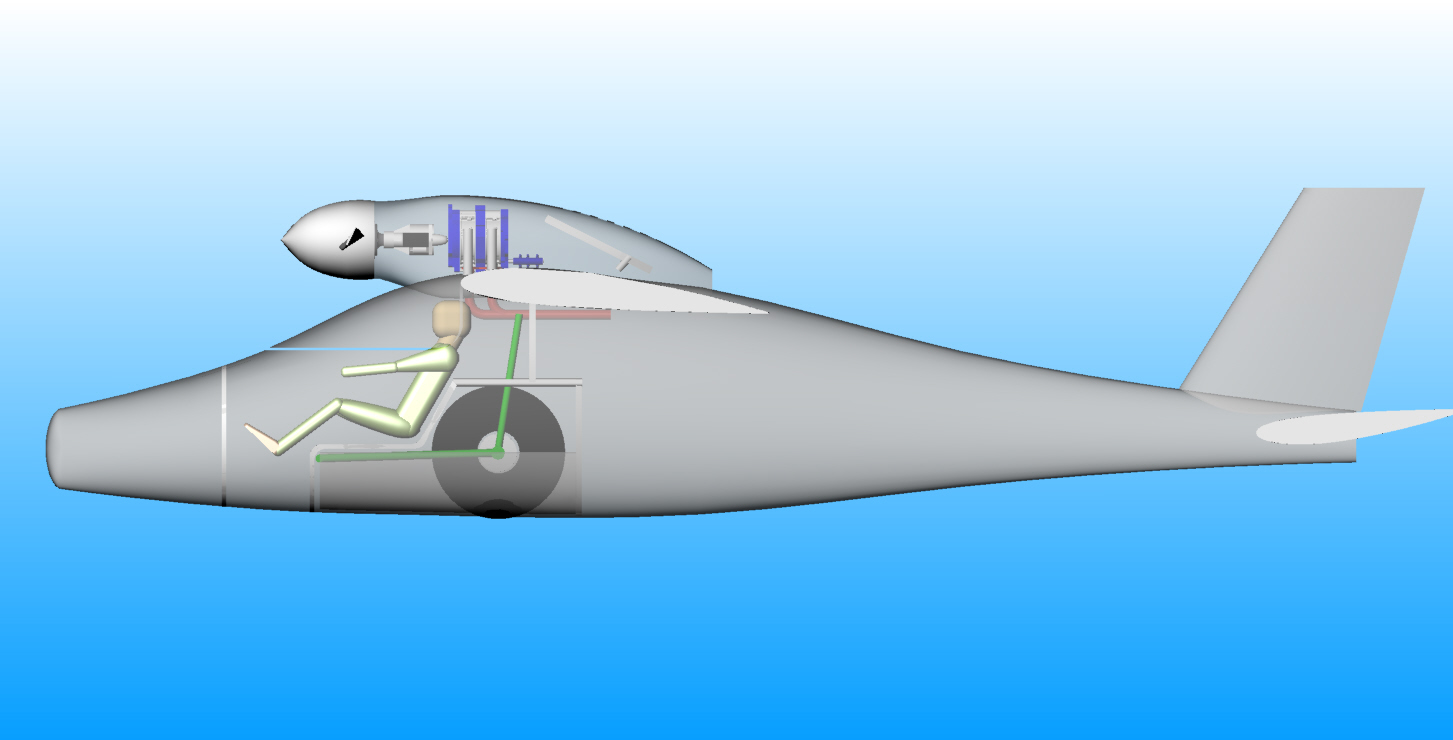
Here is my latest thinking on the fast bush plane.
I lengthened the nose and will put a baggage compartment up there.
Great for adjusting the CG with heavy loads.
It will also reduce the chance of flipping completely over if it
encounters an
obstruction too large to bounce over.
How"s your project coming. I'll loan you my 3 rotor TC if you want
to test it on your dyno.
---------------------------------------------
Here is what it looks like with the gear up.
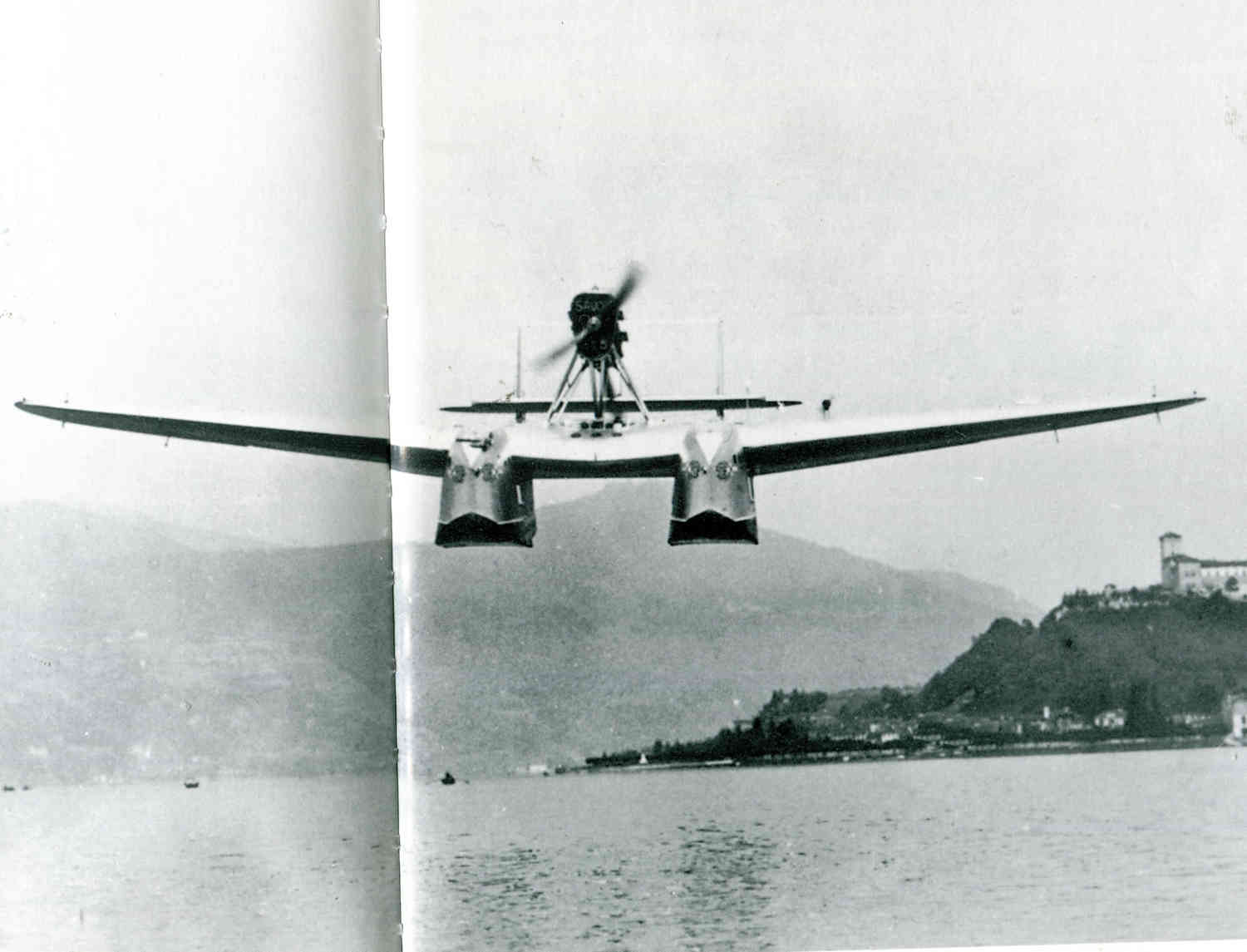
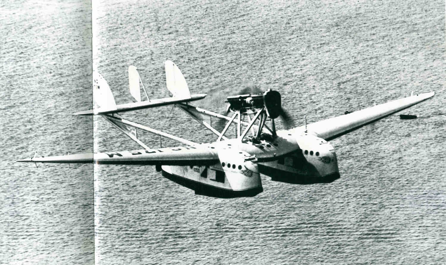
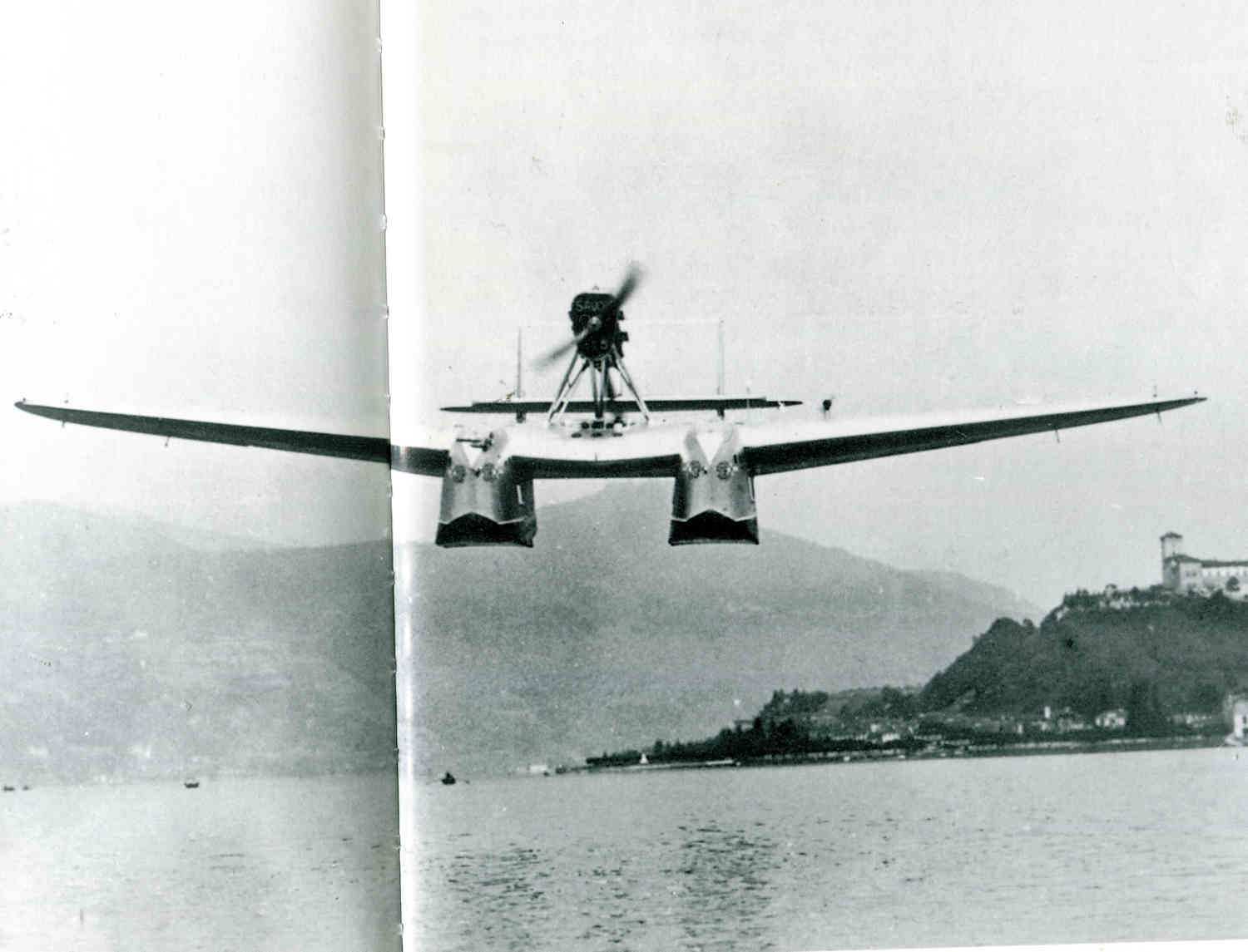
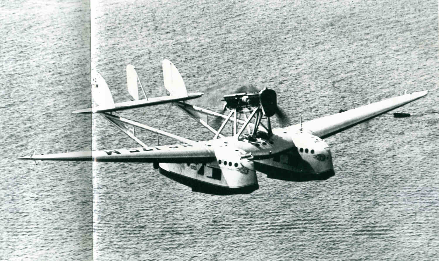
The catamaran sea plane invented by the Italians in the 1920's had/has
some unique
advantages.
"The Savoia Marchetti S.55 is probably the signature flying boat in
Italian aviation history. It is remembered both for an unusual design
and for epic overseas flights that often involved massed formations of
S.55s.
In 1923, 1Vlarchetti designed the aircraft for Societa Idrovolanti Alto
Italia (Savoia) in response to an Italian i government request for
proposals for a flying boat patrol bomber. Marchetti's innovative design
eliminated the use of a central fuselage, locating the crew and cargo
compartments in the two large pontoons which were, in effect, a pair of
30-foot, fully-enclosed boats. Across the two boats, he mounted a broad,
thick wing which contained the flight deck. Like its smaller
predecessors, but unlike other large flying boats of the era, the S.55's
wings and twin hulls were constructed entirely of wood.
The S.55P prototype first flew in August 1924, and promptly set 14 world
speed and distance records for its class. In 1927, Francesco de Pinedo
and Carlo del Prete flew a Series 1 S.55 nicknamed Santa Maria on a
27,230- mile flight around the Atlantic Ocean."
End quote.
Paul Lamar
The Rotary Engine free News Letter. Powered by Linux. If you want off
the list PLEASE let me know and I will remove you. ACRE NL web site.
http://www.rotaryeng.net You Tube
http://tinyurl.com/beqqxas
Copyright 1998-2016 All world wide rights reserved.