Hey Paul and all,
Ok I have been going thru the Sachs, I must have put it in a dozen
different positions and stared at it for hours on hours just thinking.
Now a question for you Paul specifically:
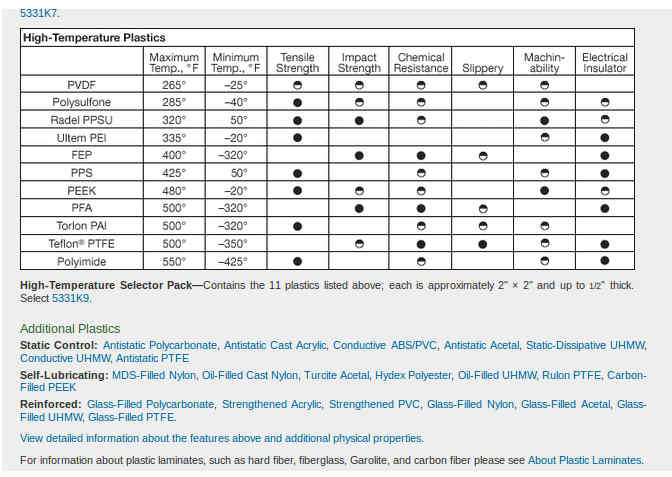
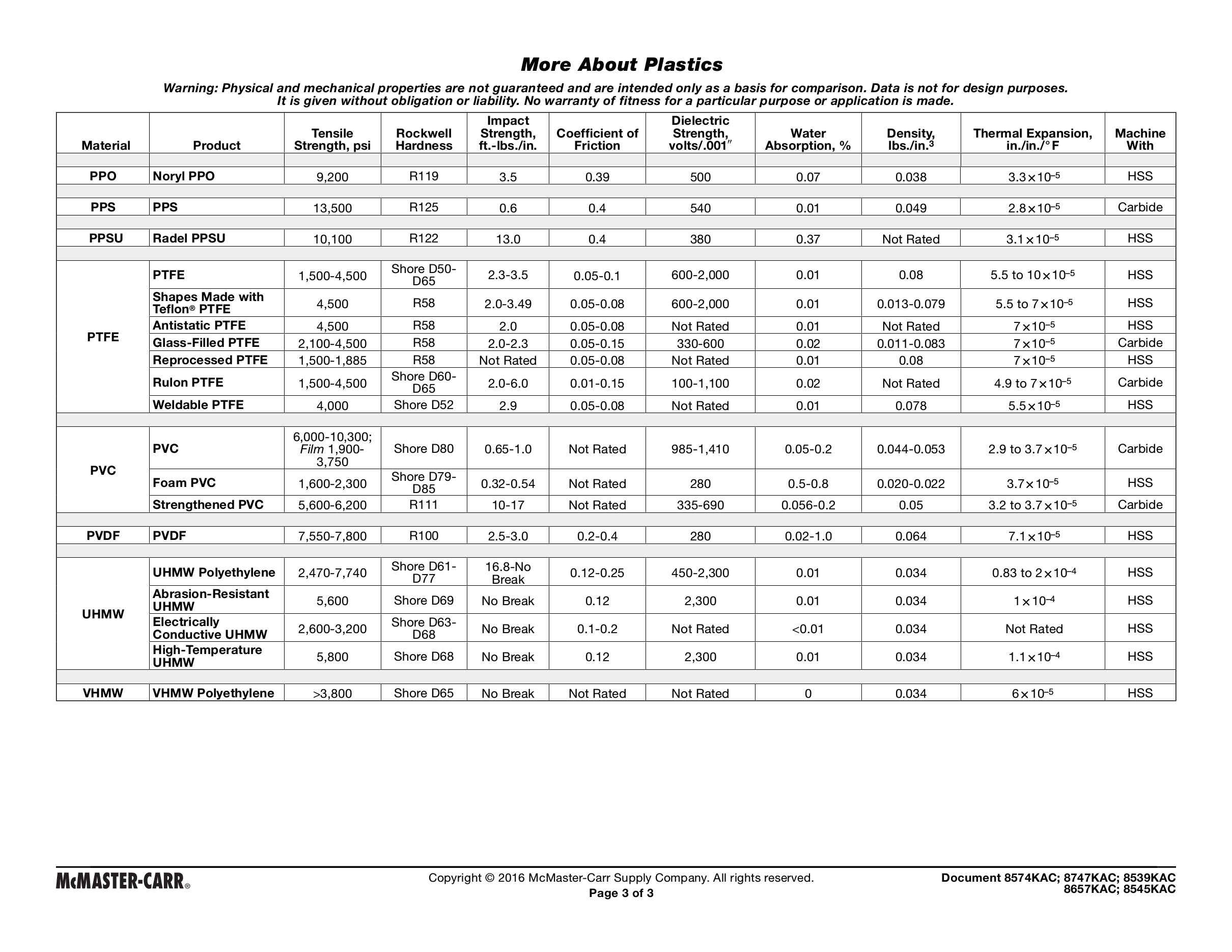
1. So the Teflon seals impregnated with glass and or carbon
fibers, what was the temperature limit for these seals?
2. Do you think it could take the temps as apex seals? (just
looking thru the papers from Mazda about combustion chamber temps) it
would be close.
3. We had talked before, and you had suggested using a thin steel
and shaping it and letting it spring into place or anchor it in place.
What about using a thicker say .125 stainless steel sheet, put it
through a roller to shape it properly and then freeze it, heat the rotor
housing and slip the two together using Hysol or some other structural
adhesive that will take high temps? The SS will help raise the BSFC and
keep more of the heat in the combustion chamber.
The only problem I see is welding the two ends ends of the SS sheet
in such a manner to try and prevent it cracking and coming free.
For everyone:
I have been mulling around the bearings and cooling oil and
lubrication. I have quite a bit of experience with turbine engines and
bring some of that to the mix on this project. I am thinking about using
turbine oil like we used in the lycoming turbines (T53-13B, T53-703,
T55) and the GE700 series, 23699 mil spec. I think it is thin enough
that it will flow very well, in the case it should froth/mist enough
coming off the rotor to cool the rotor, also will probably have to cover
50 to 60% of the bearing to prevent over oiling and floating the balls
and rollers, but enough of the misting oil should lubricate them fine.
Plus the oil is specifically designed for high temp.
The charge cooling ports are on the bottom side of the end plates,
so the oil injectors can be placed there plus can be used as the oil
drain ports too. I have though the rotor might need some modification to
keep oil from pooling inside, but after thinking about it no mods to the
rotor will be needed.
Also been thinking about the oil pump, I have been looking at the
georotor pump from the Onan generator. They are cheap and easy to find,
one on each end of the motor driven by the e-shaft and pumping directly
to the oil injector that is in the end plate. This set up should give us
the oil flow needed to cool the rotor without requiring too much power
from the engine.
Moving to oil cooling the rotor and away from charge cooling should
improve power. then having the housings water cooled will increase the
engine weight but with more power being produced and sustained is worth it.
Ok, so open to comments, suggestions and more ideas.
David Mikesell
Quest 1: 500F. Carbon and glass will go higher than that. Carbon
possibly higher than glass.
Quest 2: I think it is worth a try. Compared to some other solutions
it might be less expensive.
Mazda tries to keep the apex seals less than 500 F.
Steel ball bearings and iron starts to lose it's strength.
Silicon Nitride ball bearings are good to 1000 F.
I suspect the same thing is true for silicon nitride apex seals.
In that case there is something to be gained by alloying the combustion
chamber walls to run higher than 500 F. This would let out aluminum.
The Mazda walls are of course steel so a steel liners for the Sach and
OMC are advisable. The steel liners in the Mazda are grooved on the
out side. This allows a higher heat transfer rate to the aluminum.
If one pressed a steel liner in the OMC or Sach it would run higher
temperature. Combined with silicon nitride seals that combination
might work and show better BSFC in the bargain.
If you made it .125 one could machine the trochoide part in an
NC mill and the outside part could be simpler shape like two circles
with a straight part between them. It would be best if the inside
would be reverse chrome plated. This was done in WW II for Navy
radial engines. Same as the Mazda. The side housing could be a simple
sandwich of flat steel chrome plated and the original aluminum.
As far as I know nobody has tried this combination with less
cooling so far and did any data gathering.
Paul Lamar
Paul, and group,
Teflon is only good for VERY SHORT times at 500°F. It also has a
tendency to cold flow under pressure. Both bad things in an apex seal.
Also while the exposure is short the time that the seal is exposed to
the exhaust flow will likely erode it.
The seal itself has to transfer heat to the rotor and the housing to
control the temperature. Only the ceramic seals could likely stand the
full brunt of combustion temperatures. With plastic seals you are
experimenting and WILL get failures. You can machine a iron seal MUCH
easier than moulding one, (a good plastic seal), why re-invent the
wheel? Ceramic is out of the abilities of most places, but iron isn't.
If I needed seals for a small rotary I would look at the stock Mazda
seals and see how hard it would be to machine them down for my engine.
We know they work. And even cryogenic treated iron is very workable
Here is a question I have had for a while. On the Le Mans engine did
they even use the iron/steel liner in the housing? The SAE paper shows
the housing surface highlighted as an area using the Detonation Gun
coating. would they have bothered if the housing had the typical steel
and chrome coating? Just askin'. If we could apply a coating to an
aluminum housing directly it would make Det. Gun coating much more
attractive despite it's high price.
Bill Jepson
I think the carbon fibre will change some of the characteristic of just
teflon.
It would be cheap to try it and see what happens.
Torlon is another high temp plastic and they make ball bearings out of it
for use in sail boat blocks and winches. It is a lot harder than Teflon.
There are a lot of combinations being tried with carbon fiber fillings.
Paul Lamar
The Rotary Engine free News Letter. Powered by Linux. If you want off
the list PLEASE let me know and I will remove you. ACRE NL web
site.
http://www.rotaryeng.net You Tube
http://tinyurl.com/beqqxas
Copyright 1998-2016 All world wide rights reserved.