My Morse taper gave out when drilling brass on my CC lathe. The drill
digs
into the brass and then the taper slips. It took me hours to drill a 2
inch hole in
the 3/4 thick aluminum bar shown keeping the taper chuck from rotating.
It holds when drilling aluminum or steel.
The reason for the brass interior part was because aluminum
would generate yellow snot when flowing methanol.
These injector holders are high precision. The adjustable 3 jaw
chuck on my CC lathe was under a 1/2 thou run out. This design would
not be possible with out that.
Basically it is built around 37 degree flare fitting AN-6 to 1/4 inch
pipe steel adapter from McMaster Carr. Under $3 each.
And 5/8 diameter brass rod insert. That had to be machined down
as the diameter tolerance was all over the lot.
In terms of hours of engineering, design and machining at $50 an hour
they are
worth well over $500 each :-)
The tiny drilled head SS 6-32 screws are also from MacMaster.
This was a precision operation as well as the hole depth for the
screws was limited to exactly .2 inches or one would have a
150 psi leak. There are only about 6 threads in the hole.
Once they are safety wired they just act as retaining pins.
The mechanic better go easy with the screw driver :-)
The .040 aluminum straps holding the whole works together are not shown.
They will be tig welded to the large intake tubes.
This 200 pound 2 rotor engine is generating 650 HP with only four
injectors. PAC in Oz used
eight for some strange reason. Maybe they have not heard about the
Bosch 2000 injectors :-) Maybe that was for a 4 rotor.
Paul Lamar
Paul,
How is the brass insert sealed to the steel AN-6 fitting
??........."O" ring ??......
Kelly Troyer
Coated with RTV and pressed in with a six ton press.
Paul Lamar
I made injector holders from an AN-4 part like that, but made of
stainless. Only one drill process.
Robert LeClercq
Got any pictures of the injector holders you made Robert?
What was the diameter of the injector where it plugged into the fuel rail?
Mine are 13 mm or 39/64th.
Here are some pictures of Robert's rotary powered mid engine kit sports
car.
The engine is so small it is buried under the accessories :-)
Also Robert, if you have any pictures of the car with the hood and trunk
cover
on I would like to add to my collection. I was so enamored of how you
did the
mid engine transmission that I forgot to take some pictures of the car
itself :-)
Paul Lamar
Merry Christmas
Don't know what happened with that msg from you. The portion regarding
my GTM Libra sports car disappeared from all msgs.
Tried to get some pix, but my cameras SD adapter quit even tho I can
see the thumbnails. The car is from UK; the next to last one sold and
only one in US. The front and rear clamshells are not fastened down, so
the fit is only a little better when fastened.
The injector holders were drilled out to fit stock Mazda primaries and
sealed with their O rings. The alum clamp is holding them in with 2
#10-32 screws into the manifold boss.
Robert LeClercq
Looks good Robert. Here are the best of what you sent. The rest are a
bit out
of focus.
With boost of 20 psi doable with that turbo and some water and alcohol
to keep the intake temperature down to less than 150 F this car would
be brutal with 550 to 600 HP :-) You ought to drag race it. It would blow
people's mind :-) It would have better traction off the line than all
the front engine cars including the Corvettes. We found a little 12 volt
100 psi water pump on ebay for $18. That is what we are using for water
injection on the TTC. I would mix it 50 50 with alcohol.
Those injectors already look like Bosch so the 2000 might fit.
The 2000 is capable of up to 320 pounds per hour (EACH !!!)
with 130 PSI. It will take a heavy duty electric (and expensive) fuel pump
which will draw over 20 amps from the battery. That is almost a half a
HP just for the fuel pump but all we are talking about is less
than 5 seconds in the quarter mile :-)
Paul Lamar ...Very Merry Christmas
One of those inj holders that I didn't use is drilled out to .535".
Don't recall the size of the ones installed.
The fuel pump installed is a Mallory 110FI. Already have h2o inj
installed. I'm using an Ulka vibrating pump. Very small. Atomizing
nozzles from McM-C. 2 stage solenoid valves allow 3 flow rates. It's
well suited to the flow and pressure, up to 400CC/min @110PSI. Designed
a circuit to drive in from 14Vdc.
Robert LeClercq
Paul,
Got my notes on the injectors installed. Pri; Siemens 3 016 75052,
3102, 575cc/min.
Sec Bosch 0280 150 846, xl3E-C9A, 1680cc/min. Couple more pix of the
sec injector holder.
Robert LeClercq
Much better pictures Robert. Thanks. What 37 degree flare adapter did
you use?
Is that -6 line or -4?
Paul Lamar Very Merry Christmas
The male end is AN-4. Not sure of the female end; the thread is not
AN-6, maybe 1/4NPT. I had a bunch of them handy, and they were easy to
modify. Had to trim the ends of the hex to clear the injector connector.
The sieiens injector is the same size fuel rail hole as the RX8
injector. That means the hole in the
fuel rail is .425 roughly.
3 mm is 5.1 roughly so it is harder to find the right adapter. I have
dash 6 to 1/4 NPT and tye NPT side is
a bit too large for 5.1. That is why I added the brass insert.
The dash 4 and those injector will limit your HP I think. What is
1680cc/min in pounds
per hour? The pounds per hour seems to be the standard for injectors.
1690 x 60 is about 100,000 cc per hour. Is that 100 liters per hour?
Since there is about 4 liters per gallon that is about 25 gallons
of fuel per hour per injector. Fuel weighs about 6 pounds per gallon
so the injector is good for 150 pounds per hour. Check my logic and
arithmetic.
When a rotary is at full chat the BSFC can be as high as .8.
That means .8 pounds of fuel is burned for every HP for every
hour. 650 HP would be 520 pounds of fuel. 4 injector are
600 pounds of fuel so the injectors are a bit marginal.
That is why Jim chose the 320 pound Bosch 2000 injectors and dash 6 lines
for the TTC engine.
Not to mention the methanol effect which adds volume to the fuel.
Paul Lamar
The pri is 55#/hr; sec is 160#/hr. So 387#/hr @90% duty factor. 483hp. I
don't expect that much. I'm not using methanol. The -4 lines are short
branches, about 10" each ; pri and sec branches are fed from separate -6
lines, tank to pump to regulator are-8.
I'm having fits with trying to get coolant to circulate, even added an
elec coolant pump near radiator inlet. No flow at all. Plumbing is
mostly 1.5"OD thinwall alum, but lots of bends, Race Beat suggests
remove (new+tested) thermostat.
BTW the cobbled together ignition circuit you saw a few yrs ago is
almost ready to try on an engine. 2 PCB's; drives 4 coils (coil near
plug not COP); rotary or 4 cyl.
Robert LeClercq
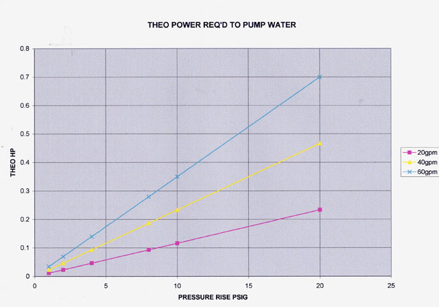
You need 3 HP to get the coolant to flow. 30 amp fuse in an electric
pump is only
good for 360 watts or 1/2 a HP.
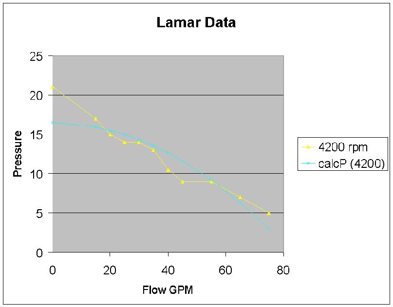
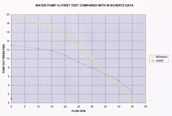
This is a water pump dyno built by the late great Vance Jaqua.
I may have some water pump casting left. If I find
them I will send you one for a Christmas present :-)
Kyle Monahan is getting 300 HP per rotor on gasoline.
Paul Lamar
I followed you closely on the pump discussion, long ago. The pump I
installed is in
series with the engine pump, at opposite ends of the flow path. Will be
trying it also
without the thermostat in about a week.
Robert LeClercq
Have you had the engine apart? Maybe the water jacket is rusted up or
the aluminum
part is corroded.
You need the thermostat in a car more than in an airplane,
After we ported a 2nd gen water pump Mazda made the RX8 water pump
much less restrictive. For the new people this is what we did to the 2nd
gen water
pump. This is only for aircraft as it does away with the thermostat.
Engine temperature can be controlled with cowl flaps. A much more
efficient way of doing it in the sense that over all aerodynamic drag
is reduced when you don't need all the cooling.
I took it a step further on my RV4 and had the water from the block
come out of the top of the pump which is a more direct path.
This increases the flow or reduces the pump HP required. Not all
airplane have the room under the cowl needed to do this.
Paul Lamar
Engine is rebuilt with new rotor housings; no rust. My pump is the rev
rotation model.
Thanx for the pump offer; have one I can send to you.
Robert LeClercq
"My pump is the rev rotation model. "
I am not sure I have heard of that. Got any pictures?
Paul Lamar
Pump is driven from the backside of the accessory belt; so reverse
rotation.
Don't know what yr models are that way
Robert LeClercq
I think it is the 3rd gen. Take a look in side and see if the right
rotor is in there.
How are you routing the belt? The stock 3rd gen has an air pump I think.
Is that a stock 3rd gen turbo charger?
Paul Lamar
I did take care to check the impeller. Seem to recall the pump front
cover has a different bolt pattern than others. Single drive belt is 8
rib. Alternator is placed close to the water pump side and its pulley is
higher than the pump pulley. Pump pulley has more than 90 degrees wrap
to the belt. Don't think there is any slippage. Hard to get a pic of it .
Robert LeClercq
Turbo is a modified Garrett T4. Water cooled. I lost my turbo websites;
can't recall the details. Compressor is 70 or 72mm. Turbine outlet was
machined out and a bigger size V band outlet welded in. Turbine wheel is
1.0 trim. Maybe made by Precision Turbo?
Robert LeClercq
Paul
I lost the attachments containing the pump dyno; etc. Can you tell me
what outlet pressure to expect from the engine driven pump at idle? I
had installed pressure gauges on both inlet and outlet a couple wks ago.
With the engine starting from cold (thermo closed) I only saw about 1
psi on both. Temp rose in about 2 mins to where the thermo should open;
then both gauges read about 6 psi and the pressure cap released coolant
in less than a minute. Didn't see a pressure differential, but had to
shut it down. Both pipes under the car leading to and from the rad were
still cold.
Robert LeClercq
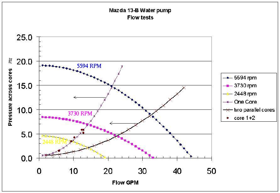
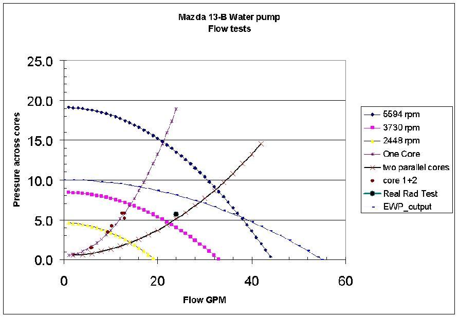
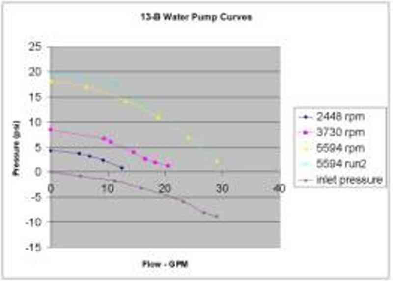
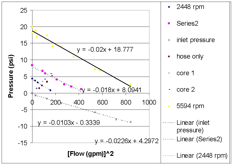
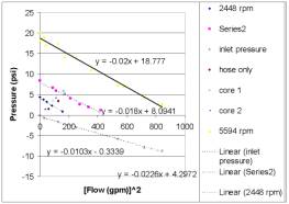
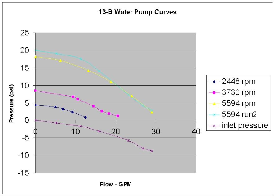
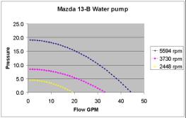
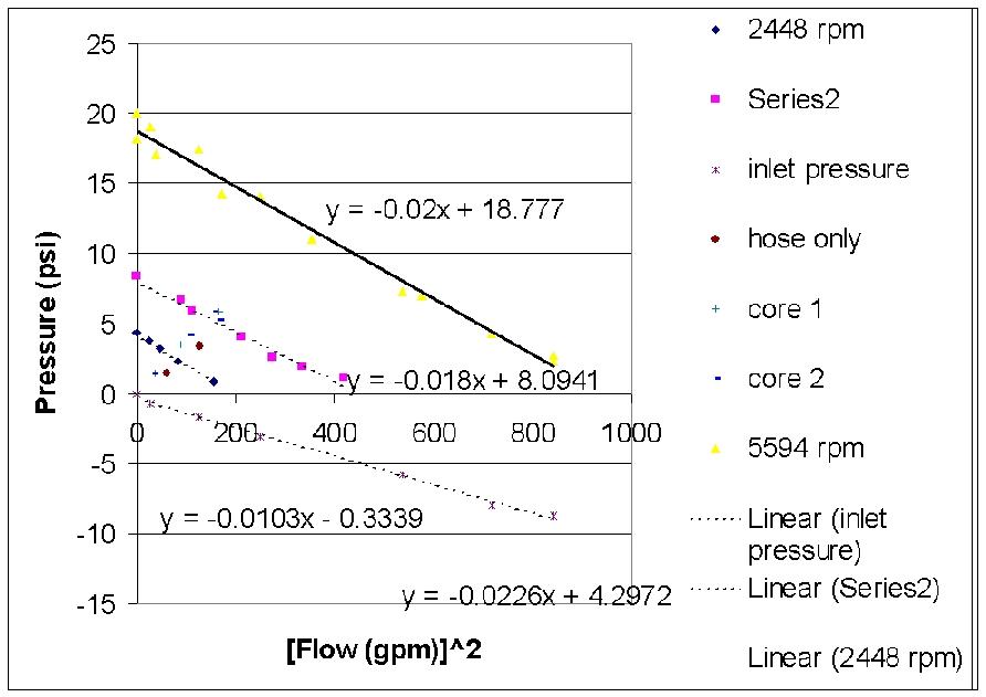
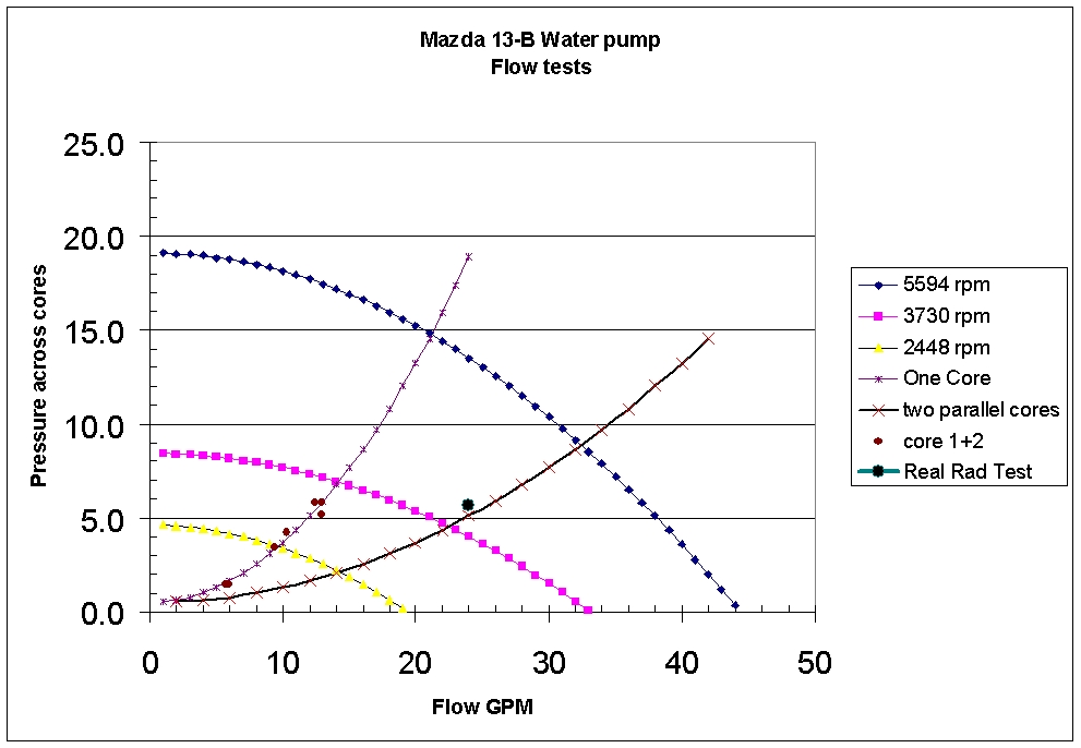
The pressure on a centrifugal pump is a question of flow. Too much
restriction too little flow and then they
cavitate.
That phenomena is not shown in these charts because it is a question of
where snf how you measure the
pressure. We see that all the time in the TTC fuel system when running
on the boost pump.
If you block the out put on a positive displacement mechanical pump the
drive shaft will fail if the hoses don't burst first :-)
Here is a bunch of data.
Paul Lamar
The Rotary Engine free News Letter. Powered by Linux. If you want off
the list PLEASE let me know and I will remove you. ACRE NL web
site.
http://www.rotaryeng.net <http://www.rotaryeng.net/>You Tube
http://tinyurl.com/beqqxas
Copyright 1998-2016 All world wide rights reserved.


