Implementation of a Rotary Engine (Wankel Engine) in a CFD Simulation
Tool with Special Emphasis on Combustion and Flow Phenomena
2015-01-0382 Published 04/14/2015
IMHO This is the best technical paper on the Wankel so far.
Frank Herfert found it. Thanks Frank.
"In summary, the loss analysis shows that the main losses of the
Wankel engine result from the protracted and retarded combustion.
Consequently, the wall heat losses are lower than expected. "
" The mechanical losses, as well as the gas exchange losses, are
lower than comparable conventional spark ignition reciprocating
engines. The comparison between the investigated Wankel engine and a
normally aspirated, throttle-controlled gasoline engine with port
fuel injection under full load and high revolutions, is illustrated
in Figure 37."
"The largest deficits of the Wankel engine can be found in the area
of combustion (implementation loss due to incomplete implementation
of the fuel and combustion loss ) and leakage loss. The lower wall
heat release loss , compared to the conventional gasoline engine,
results from the late and delayed combustion. The lower mechanical
losses and charge exchange losses arise from the port control and
consequently, absence of the valve train."
What they did not investigate was multiple sparks on the same spark
plugs or more spark plugs. In effect, unlike a piston engine, the
combustion travels past the spark plugs. In a piston engine the
combustion moves away from the spark plugs some what.
That is where my new high speed CD ignition system comes in to play.
It is capable of firing the plugs six times.....five degrees apart
at 8000 RPM. Patent is still pending.
It can be tested now, on a dyno, using multiple MSD capacitor
discharge ignition systems fired by a high speed computer 5 degrees
apart at 6 to 8K RPM.
I do not have a dyno to test this but I can supply the control
computer. Simon Saba has a rotary engine dyno in northern
California. Please Simon, see if you can get the money to try this.
Paul Lamar
Hi!: as discussed, I requested Kevin Landers, from
RotaryResurrection, to implement the Fujikawa, Kawasaki, combustion
promoting improvement plug hole triangular extension, pointing to the
trailing side of working chamber (Patent 3848574, of 1974), but it
took over one year for the tuned 1987 13B NA the engine to arrive
from NJ to Barcelona, and it's still pending to be installed in my
1976 AMC Pacer Sedan, along with a Mazda RX-7 four speed plus reverse
automatic transmission, if the project is concluded, I'll try making
a comparative test with an ordinary 6-L 4.2 liter AMC Pacer, and let
you know results.
Thanks, have a nice 2017, best regards, + Salut †
Jose Gros-Aymerich
E-28033 Madrid, Spain
I don't think you will learn much Jose.
The best BSFC islands are in entirely different places for the Pacer and
the RX7.
The Pacer has much more frontal area and the drag coefficient is much higher
than the RX7.
Paul Lamar
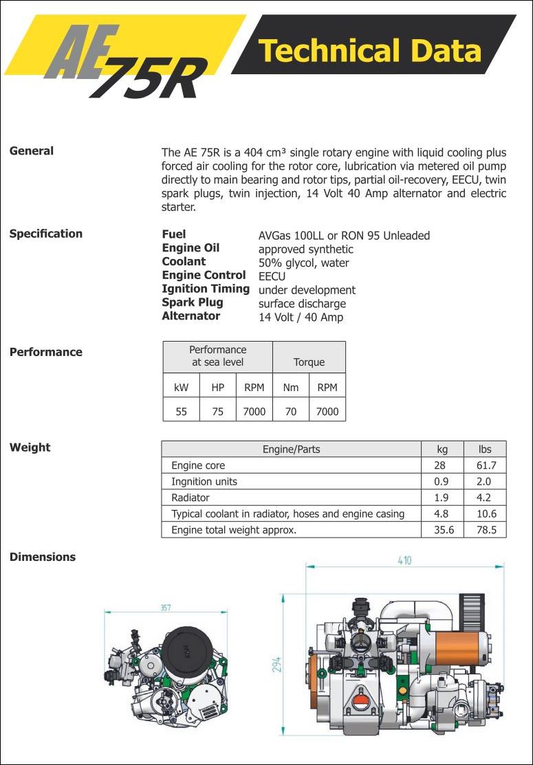
Hello Paul, I think of Austro Engine because at the end of the first
paragraph of the Introduction the Austro Engine Company is called the
research partner of the Technical University of Vienna ... If you have a
look at table 2, the Vc is 404 cc - exactly the volume, Austro engine
has given in the description of 2009 - please see the enclosed
screenshot. It must be an existing engine, because they have it run on a
test bed ... But the 407 cc engine from the Wankel AG has a width of 6,5
cm, not 7,44 cm. So I've guessed, that it's the AE75R prototype ;-)
Perhaps there is yet another engine of this size - of course I do not
know all RE in the world today ;-)
But I think, that it's not very important, which engine they've analysed
in Vienna.
Their work is rearly serious - without "pink glasses".
It's a good base for further development ...
I have a "strange" idea related to the trailing section problem -
perhaps I will try to explain it with Paint, although I think, the
mechanics will not work / will not be feasible ... ;-)
Yours very truly - I wish you a perfect start into the new year
Franky / Frank Herfert
I was at the Austro engines factory in 2001.
Here are some pictures.
Paul Lamar
On that graph with blue red colors I am not sure what is meant by
'Implementation loss'.
Item 3 does not sound to be right. The wall surfaces of the Wankel are
admittedly larger than on the RPE.
Hello Franky. If you can show your idea, then pass it by us, but only if
it is not confidential. Or, if you would like, get back to me privately.
Paul may pass on my email address.
Rolf Pfeiffer
"Efficiency Loss Due to Combustion Loss
The real combustion in the engine is not isochoric and does not take
place at TDC. Thus, this loss can be divided into two.
Efficiency loss due to the center of heat release
According to. 42 it is assumed that the energy conversion takes
place isochorically, but not at the TDC, but based on the real position
of the MBF50 of combustion.
Efficiency loss due to real heat release
In this step, the real duration and shape of the heat release is
considered. In Figure 32, areas that are enclosed between isochoric
and real combustion processes are marked. These have to be
accumulated and considered as loss."
Here is fig 32.
The reason the wall loses are lower is the energy loss in the
combustion results in less heat getting into the walls compared
to a piston engine. It would probably be higher if the combustion
was improved. We are very close. Ignition of all the mixture
as soon as possible is the key. Surface mount spark plugs well
a head of TDC would help greatly. The Mazda Lemans had
3 spark plugs the third being head of the regular two.
I have suspected this for years. Here is a drawing I did in 1998.
Paul Lamar
Hello Paul,
it's after one o'clock in the night now - so I will only send "some remarks"
... ;-)
Enclosed you will find the Screen shot, I've talked about - I've simply
forgotten it - sorry, sorry ... ;-)
To Rolf ...
I have the book you've described - it's written in a positive point of view
+ that's ok ... ;-)
Unfortunately there are only a few books available - e.g. by Ulrich Knapp,
2006, Waxmann Verlag GmbH, ISBN 3-8309-1637-x, with interesting details ...
(German)
I don't think, that my "idea" is worth to be discussed seriously - will more
a kind of joke - well, on paper there's everything possible, but in reality
... ;-)
__________
To Jose in Madrid ...
the figures in the patent US 3.848.574 are showing a rather big opening - so
the question is, how much blow back there will be ...
Perhaps you get in trouble with hot residual burning gases, that "find"
their way into the following chamber - means danger of preignition far
before TC + "negative torque" ...
Or you will loose some fresh mixture out of the following chamber into the
leading exhausting one ...
Generally you can say, the smaller your "openings" for ignition or
injection, the "better" ...
But since you haven't tried it, you can't be shure ... ;-)
May be, that you can transfer some unburned rich mixture from the
"forerunner" to the following chamber - you can see an example in the
preview of the SAE paper 2007-32-0098 (small RE for unmanned helicopter)...
___________
Combustion in general ...
the "up+down" freaks are using turbulences since may be 70 years. With some
swirls / vortexes / eddys you can speed up the combustion "dramatically",
but you will also get more heat losses to the walls - again "the dose is the
decisive factor" ... ;-)
And: flow speed is not the same as turbulence. In the first case a
relatively thin flame front with only a little active surface "is blown
forward through the mixture", in the other case you have a big / wide active
surface - a bit like chain reactions in many different directions, even a
very little bit against the flow direction ...
Of course, a strong ignition source will help, too. There are a lot of ideas
with + without active or passive "pre chambers" to study + then there are
the ideas by the "Plasma guild" ... ;-)
At the end the relationship between costs + the gain you may see is the most
important thing. So, perhaps it's better to wait until Paul's new ignition
system is available ... ;-)
But, I think, there are a lot of other people, that do know much, much more
about combustion kinematics + chemical reactions ... (Dale Davies ?)
Btw: avoiding leaded AvGas for RE is a good idea for two reasons ...
- lead hinders the fast + proper "growing" of the oil film on the trochoid
surface (less important in Mazda engines since 1986)
- lead is a combustion retarder - it slows the burning speed (therefore it
was used as "anti knock solution" in the last century ...)
Now it's late enough here in "old europe" ;-)
With kindest regards
Franky / Frank Herfert
That patent is so old (1974) that over 2.5 million Mazda engines have
been sold since
then. If it had worked it would be used by now.
Good point on the lead. In theory aviation fuel is now low lead but I
wonder what
they use now to retard knock.
The choice of the Austro engine for research is a bad choice as they use
high pressure
air to cool the rotor and rotor bearing instead of oil cooling. That is
a BSFC penalty of almost 10%
due to the HP consumed by the blower. That type of rotary is typically
.53 BSFC while
a Mazda is .47 BSFC. lbs/HP per hour.
A another thing about that paper is the emphasis on "squish flow".
I quote.
"Due to the squish flow, the flame propagation is retarded [11] against
the direction of rotation of the rotor and intensifies the wall heat flux.
As proved, the remaining unburned mixture combusts until it has escaped
from the
trailing part of the combustion chamber. Figure 29
shows the process described above with reference to the CFD
simulation. The flame spreads primarily in the same direction as the
rotation of the rotor. Similar results are shown in [31] and [32] based
on test bench measurements and in [16] with the help of CFD
simulation. The penetration in the opposite direction happens very
late because of the pronounced squish flow.
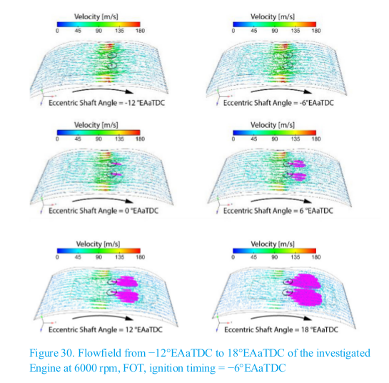
The reason is that the gas velocities of the squish flow in the region of
the flame formation move at about 70 to 180 m/s (see Figure 30),
while turbulent flame front speed as a function of pressure,
temperature and turbulence in the combustion chamber of a
conventional SI reciprocating engine has a one power lower value,
shown in [33], [34], [35], [36] and [37]."
Squish flow is easily over come by moving the bath tub to the trailing
side of the rotor. As I recall Mazda may have tried this but without
the aid of the CFD analysis.
Note the CFD's show two spark plugs side by side. The Austro engine has
a relatively wide rotor.
Paul Lamar
The Rotary Engine free News Letter. Powered by Linux. If you want off
the list PLEASE let me know and I will remove you. ACRE NL web
site.
http://www.rotaryeng.net You Tube
http://tinyurl.com/beqqxas
Copyright 1998-2016 All world wide rights reserved.