This is what the power supply cabinet looks like. The big thing on
the upper right is the 220V 3 phase circuit breaker and master
switch. All the other circuit breakers appear to be wired to this.
The spindle motor controller uses 220 3 Phase.
The servo amps get along on 110 V.
I am not going to implement the auto tool changer.
There is a cooling system which I can manual control.
In fact I can manually controls the spindle speed as well.
That greatly simplifies the system I hope. It is not like I will be
making 100 parts at a time. Just a very basic 3 axis.
What do you think David or anybody?
Paul Lamar
Sounds great. I am working on the code for HAL for your drivers.
That manual was a great help.
David M. San Jose. CA
Thanks David I forgot the picture and the docs on the Speecom. Here
they are.
I am also working on the design of the end housings. The rear is
quite simple.
The front end housing must accommodate a water pump. Does anybody
have any preferences for water pumps. 2nd gen or RX8? Or some else
perhaps?
The oil pump with be a dry sump pump with choices of several brands.
Pual
Well, that power cabinet will need to be straightened up a bit.
There should be a speed controller for your spindle already, just
need to know what it is so I can find a manual for it and hopefully
integrate it into the new CNC controller.
David Mikesell San Jose, CA
I am cleaning it out as we speak. I will make schematic of what it
is now and eliminate the unnecessary stuff which is most of it :-)
I'll put local switches on the cooling system and the tool changer.
Actually on the tool changer they are already there.
The big circuit 3 phase 220 volts breaker is also the master on and
off sw with a handle out side the cabinet.
I just sent the pdf's on the spindle motor controller.
It is called a Speecom and it was made by GE. 3HP 3 phase 220 Volt
Here they are again.
The axis tachs feed back to the servo amps so they may not need to
be interfaced to the EMC. They put out plus and minus DC volts
according to direction. They are the same tachs that worked with the
servo amps before. It is a Sierracin Magnedyne.
I'll bet some of this tech came out of remote controlled gun turrets
in WW II B29's. :-)
Paul Lamar
I am Jealous! How come no pictures.
Milo Burroughs,
I sent them later. If you did not get them I will send them again.
I just realized this Kasuga has a powered nee. That is a wonderful
thing. No fun cranking a nee up and down. Works off 110 volts so it
must have the circuitry to do that inside this control box..
David, do you recognize this servo power supply? Apparently the servo
motors do not use a lot of power. This too is powered by 110 Volts
AC. If that is true I am near done on wiring this thing once I get
HAL on the job. (Who ever or what ever that is??? :-))
The servo amp cabinet is near empty :-)
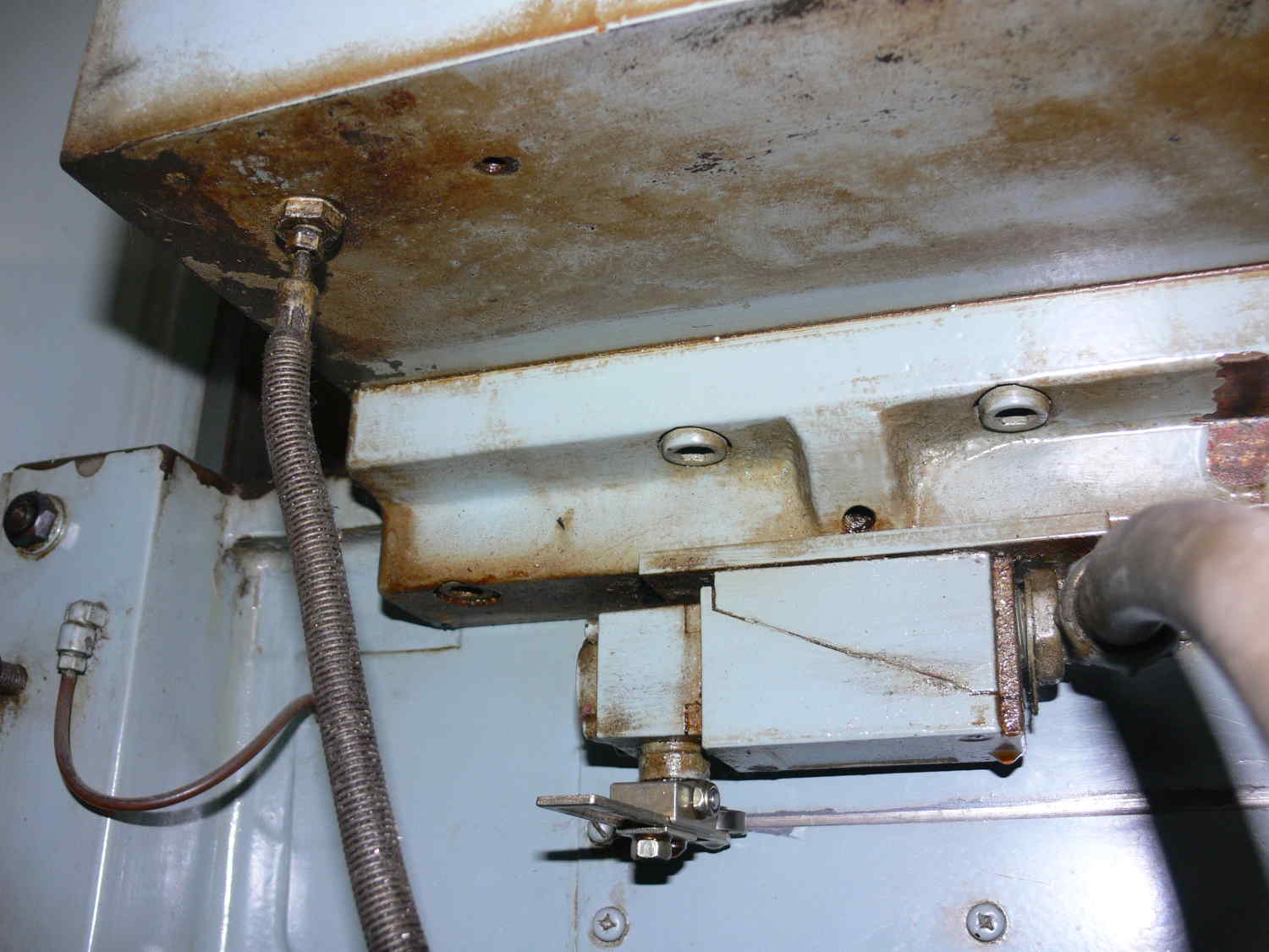
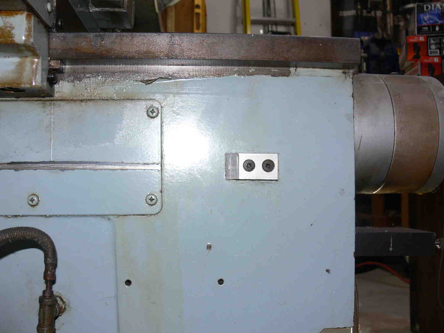
The X home switch and the X limit switches appear to be one and the
same. Is that possible David?
Paul Lamar
That knee control is your Z Axis? Or does the spindle on its own Z axis
and the power knee is just accommodate larger pieces?
I seen the flood coolant control also on your knee control box
It's not possible for them to share the same stops. just because of the
way each one moves, unless they have a neat little cam thing that
swings to trigger one axis which of the other.
David Mikesell
San Jose California
That nee motor is big. Looks like it could lift 500 pounds.
I had to get down on the floor and look up underneath to see it :-)
There is a down limit switch I think. It looks like
that shuts off when it contacts the floor if the nee down
goes too far to tilt the entire mill :-)
I love the idea of that power nee.
The 110 volt coolant pump is on the back side of
the power cabinet and there is a toggle switch for Flood, mist. and off.
Here is a picture.
The Z axis spindle has it own servo motor and amp.
The Z axis home is all the way up and there are three total switches in
there.
One for home, one for too far up and another for down.
The X axis home may be all the way left but there is just this one switch.
That is all I found on the x axis so far.
I am still looking for the limit switches on the Y axis. I found
another loose switch
not mounted yet. That may be a Y axis switch.
Paul Lamar
I found the Y axis switch David,
They are double throw center off and they move with the table.
So home must be on one end or the other.
Paul Lamar
The Rotary Engine free News Letter. Powered by Linux. If you want
off the list PLEASE let me know and I will remove you. ACRE NL web
site.
http://www.rotaryeng.net You Tube
http://tinyurl.com/beqqxas
Copyright 1998-2017 All world wide rights reserved.