It looks like a K&L wedge diffuser will work best for my
application. I am working the cowl design and I am trying to
determine the optimum opening area for inlet air. I have your book
but I cant seem to find the answer. Some time back there was some
discussion about this. If I remember correctly the consensus was 15
percent of rad area was too much. Is this correct. If so, what is a
good area for inlet air?
Paul Shamlian
I suspect it depends on the thickness of your core. What are the
dimensions of the core you plane to use? I suspect if the core is
large in area and thin 10% might work. Large area thin cores have
lower cooling drag.
The other factor is movable louvers aka cowl flaps. If you can close
the louvers, assuming the engine is cooling adequately, the drag of
an overly large opening, say 20%, is reduced by external diffusion.
If the core is thin 10% might work.
It is a good idea to use louvers or cowl flaps in any event.
Also it is a good idea to have the opening in the prop slip stream
so it will cool waiting to take off.
We are still over cooling the 650 HP TTC with 20% opening on the
ground no less.
The cross counter flow heat exchanger consist of two .75" cores 20"
by 30" back to back. No cowl flaps but a very nice set of curved
louvers.
Start with 20% and see what happens. Design the opening so it can be
closed down later. Maybe you can run it with out the final cowl.
Do you have any recent pictures of your Bear Hawk patrol Paul? Is
the core on the cool side of the engine? Does it exit through the
side of the cowl?
Paul Lamar
The radiator I am looking at has a core that is 17 X 14 with a
thickness of 2.7 inches. 642 cubic inches. I am only measuring the
core, not the overall dimensions. The best source I could find for
radiators was Summit racing. They are the same radiators we use in
circle track racing. I am modeling the firewall forward in Rhino and
trying different arrangements. There isnt room on the cool side to
make it work without a large boxy nose bowl. The rad fits under the
engine nicely and maintains a nice cowl. There isnt enough room to
have both the oil cooler and rad under the motor so the oil cooler
has neen moved to the cool side. The plan is to try to build louvers
on the bottom of the cowl for the radiator. Not yet sure how to exit
the air from the oil cooler. Hopefully just an exit duct but might
be a cowl flap Paul Shamlian
That is not going to work well. First a core that size full of water
is very heavy. Second the air has a hard time going through a core
that thick. Most car racers have not caught on yet. Dodge and Honda
are the leaders in cooling efficiency.
You have a engine weight problem already unless you are going to
aluminum end housings.
Shop this company by rad size.
https://www.radiatorexpress.com/category.asp?cat_id=R026
<
https://www.radiatorexpress.com/category.asp?cat_id=R026
Here is the 20" by 30" by 3/4 inch thick Dodge truck rad underneath
Bear Hawk Patrol 3D's. It is always harder to fit the 13B in a tandem
airplane. The RV4 is even narrower than the 32 inch wide Bear Hawk
Patrol.
I'll get the year and make so you can order year and make. It will
be about $130.
Where are you Paul?
Paul Lamar
-----------------------------------------------------------------------------------------------
Hear is the core to use Paul. You may need to weld on new header tanks.
You may get away with as little as a 10% opening.
Paul Lamar ---------------------------------------------------- I
recently ran across a lot of old (1972) data on rad cores. This is
the kind of data Kays & London used to draw conclusions. I covered
them and their conclusions extensively in my book "How to Cool Your
Wankel".
Note the difference in pressure drop between a 3 inch thick core and
a 6 inch thick core.
Pressure drop in the cores is one and the same as cooling drag.
Paul Lamar
If I understand the graphs correctly, the velocity of air through a
core will double if the thickness is cut in half.
So would that mean
that drag will be reduced by four times if the thickness of the core
is cut in half?
Paul Shamlian
Sent1:
"If I understand the graphs correctly, the velocity of air through a
core will double if the thickness is cut in half. "
On the face of it yes. But you are starting with a constant velocity
more or less.
Sent2:
"So would that mean that drag will be reduced by four times if the
thickness of the core is cut in half?"
NO! Drag on a given surface area is proportional to velocity squared.
When the thickness cut in half, the metal area the air flows over
to create the drag, is cut in half. However it is necessary to double the
frontal area of the core to restore the needed cooling affect and to
restore the heat transfer metal area.
What actually happens is: as the cooling air flows through a core the
air is warmed
reducing the heat transfer rate from metal to air.
The rule of thumb is the first half of the core does three quarters of the
cooling.
It is a complicated situation and all factors must be considered.
It took a couple Phd's 20 years to write the book :-)
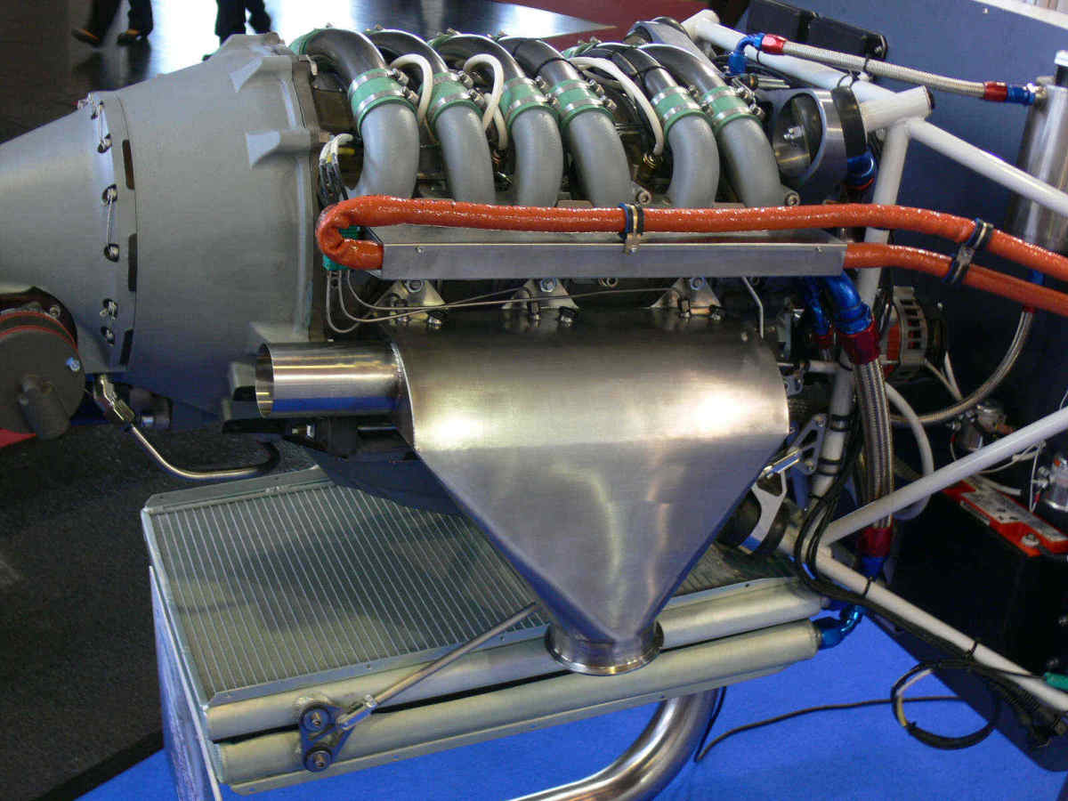
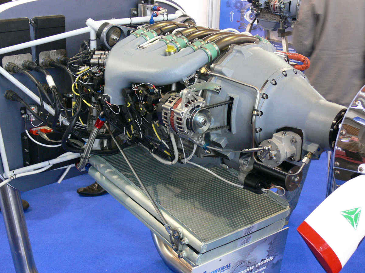
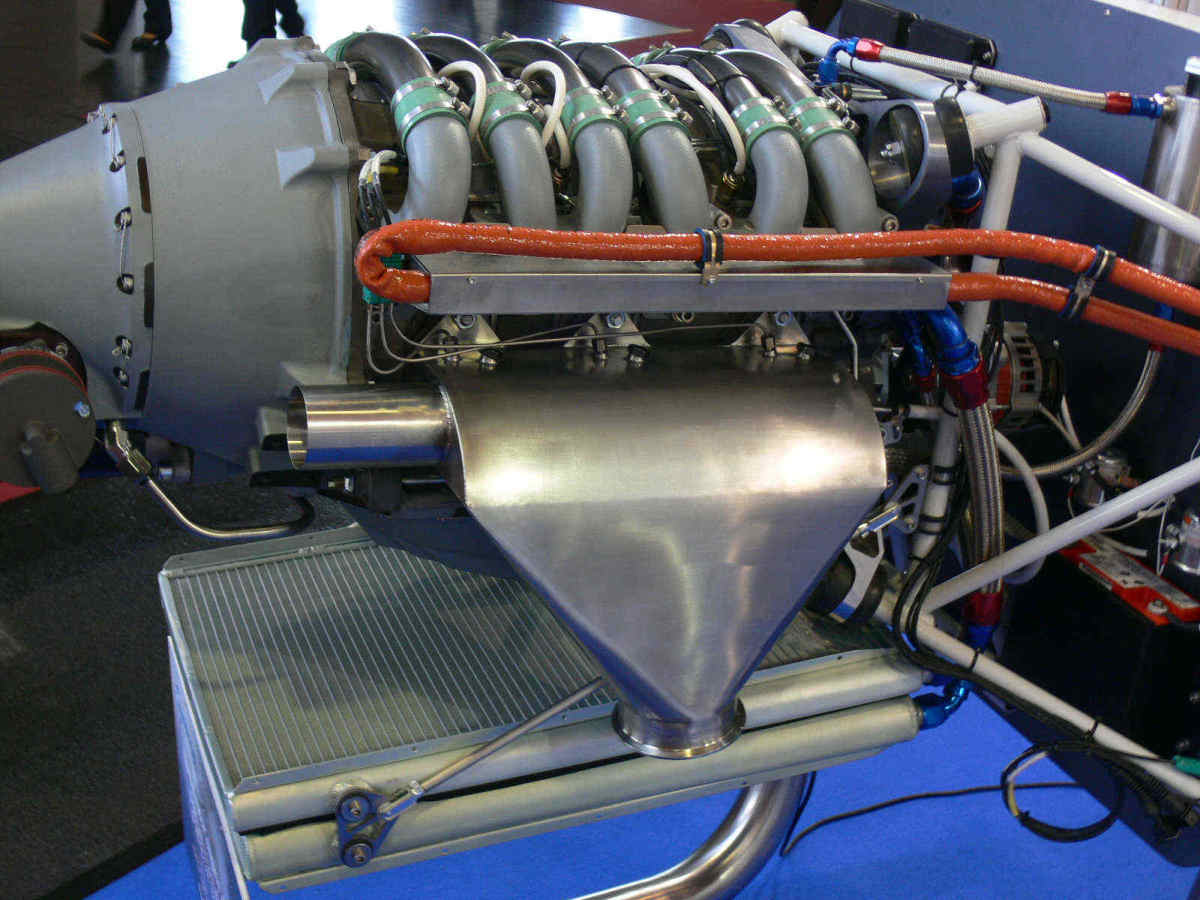
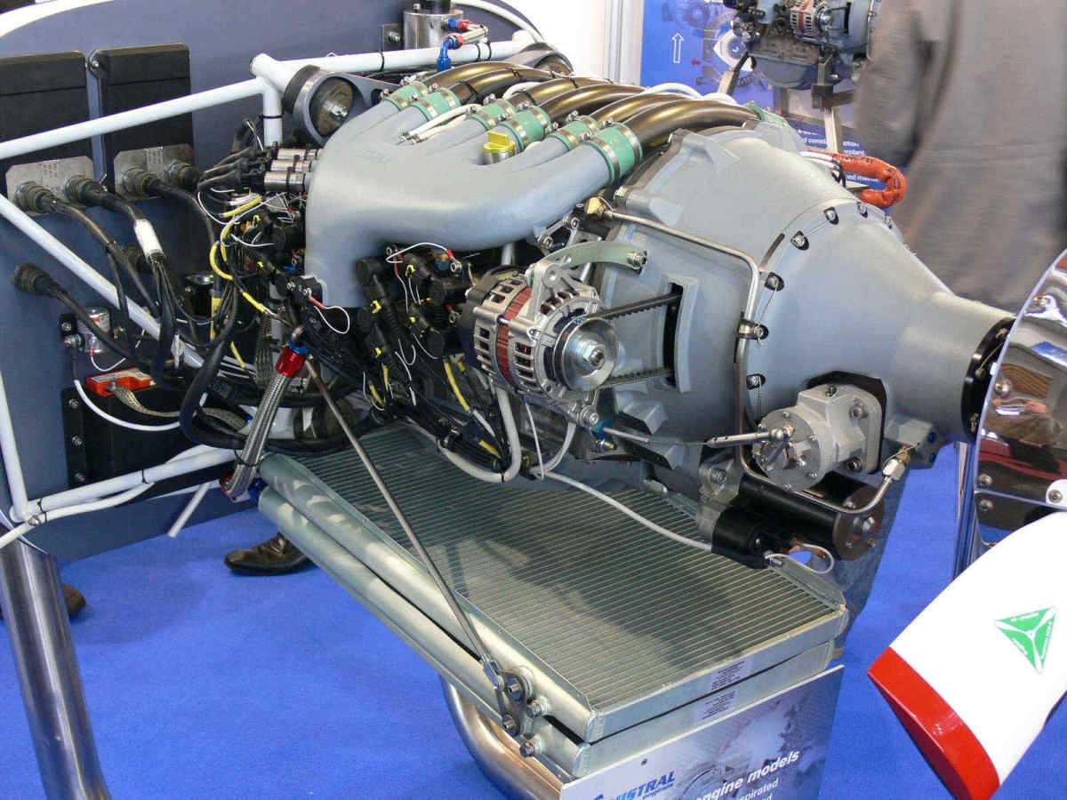
Mistral caught on. Here are some pictures of their preferred cooling system
less the K & L diffuser.
Paul Lamar
The Rotary Engine free News Letter. Powered by Linux. If you want off
the list PLEASE let me know and I will remove you. ACRE NL web
site.
http://www.rotaryeng.net You Tube
http://tinyurl.com/beqqxas
Copyright 1998-2017 All world wide rights reserved.