Paul, do you or anyone on the group remember the change in crankshaft
resistance after torquing down the RD 1C 12" an4 bolts at final assembly?
The assembly instructions show a trial fitting without the 5 1/8 inch
ring gear spacer o-ring. This worked well on my unit, with the
crankshaft turning easily by hand. However I found this oring was
missing from my unit.
Tracy's specifications are for a 5 1/8 inch outside diameter and 0.190
inch thickness, which corresponds to an AS568-351 (3/16" thick). I
ordered some of these, but found that the actual thickness is 0.21
inches, not 0.190". I cannot find any metric or other equivalent size
that exactly matches the 0.190 specification.
When tightening down the drive bolts to the final torque, the
resistance to turn the crank shaft roughly doubled. I can still detect
just a little bit of backlash play, but the torque required to turn the
crank shaft without spark plugs installed is approximately 20 foot
pounds. It appears this is due to the resistance of the ring gear
pressing on the O-ring against the adapter housing.
Does anyone know if this amount of resistance is normal, or perhaps
Tracy was using some o-rings that are exactly 0.190 inches in thickness?
Thanks!
Scott Gettings
I assume that is the late one that does away with the torque damper.
I have no experience with that one. Send me a dwg or sketch if you can.
A picture or two would also help.
Typical of O-ring dimensions. It gets real critical when you are
dealing with the rotor housing
O-rings. Too big and it will crack the cast iron.
I this case it's not that bad.
Paul Lamar
The RD1 C still has the 4-bolt damper that mounts to the flex plate. I added AN 970 large washers to the bolts on the engine side to the plate, which was obviously highly stressed by the bolts and standard washers on that side. It is also easy to inspect.
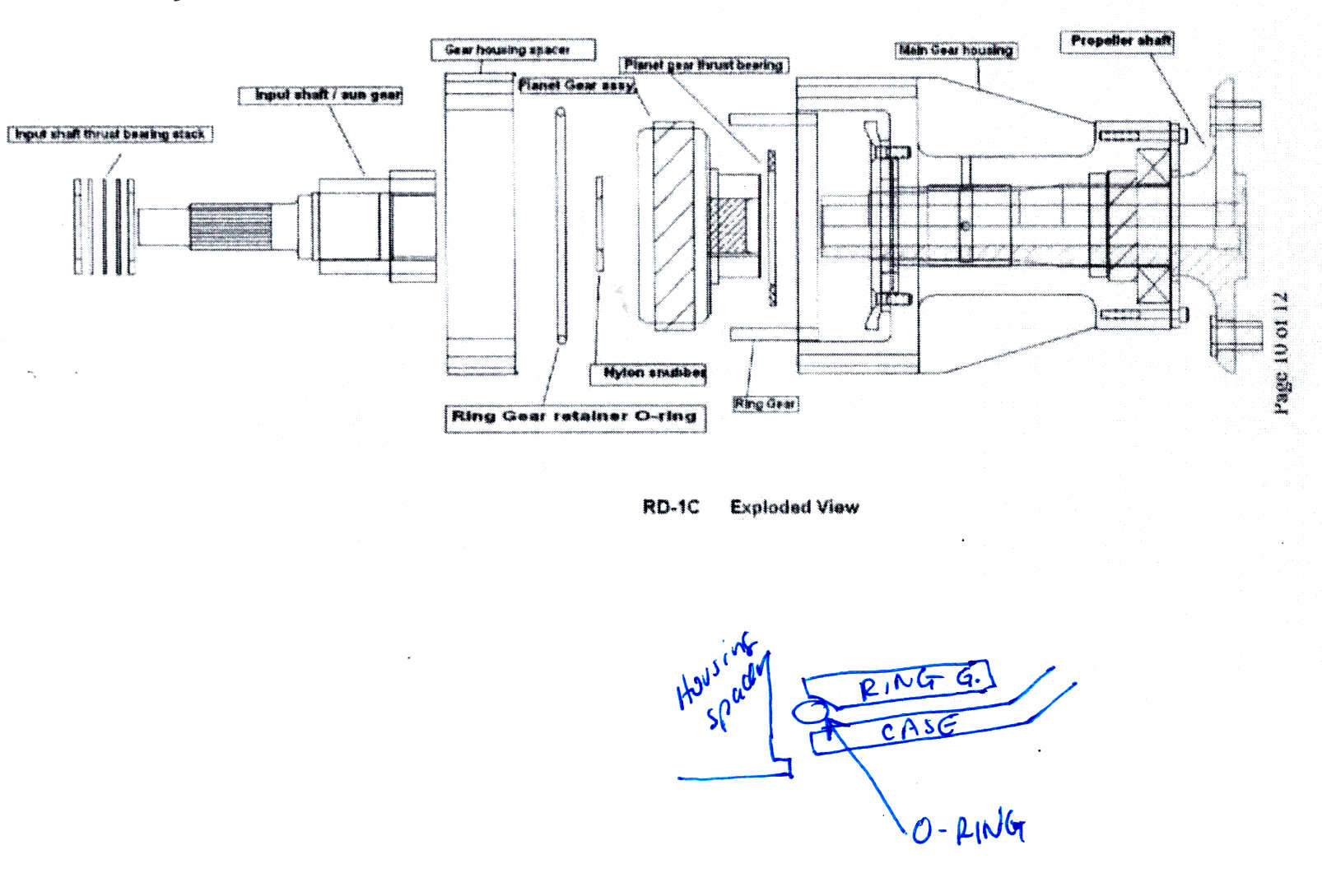
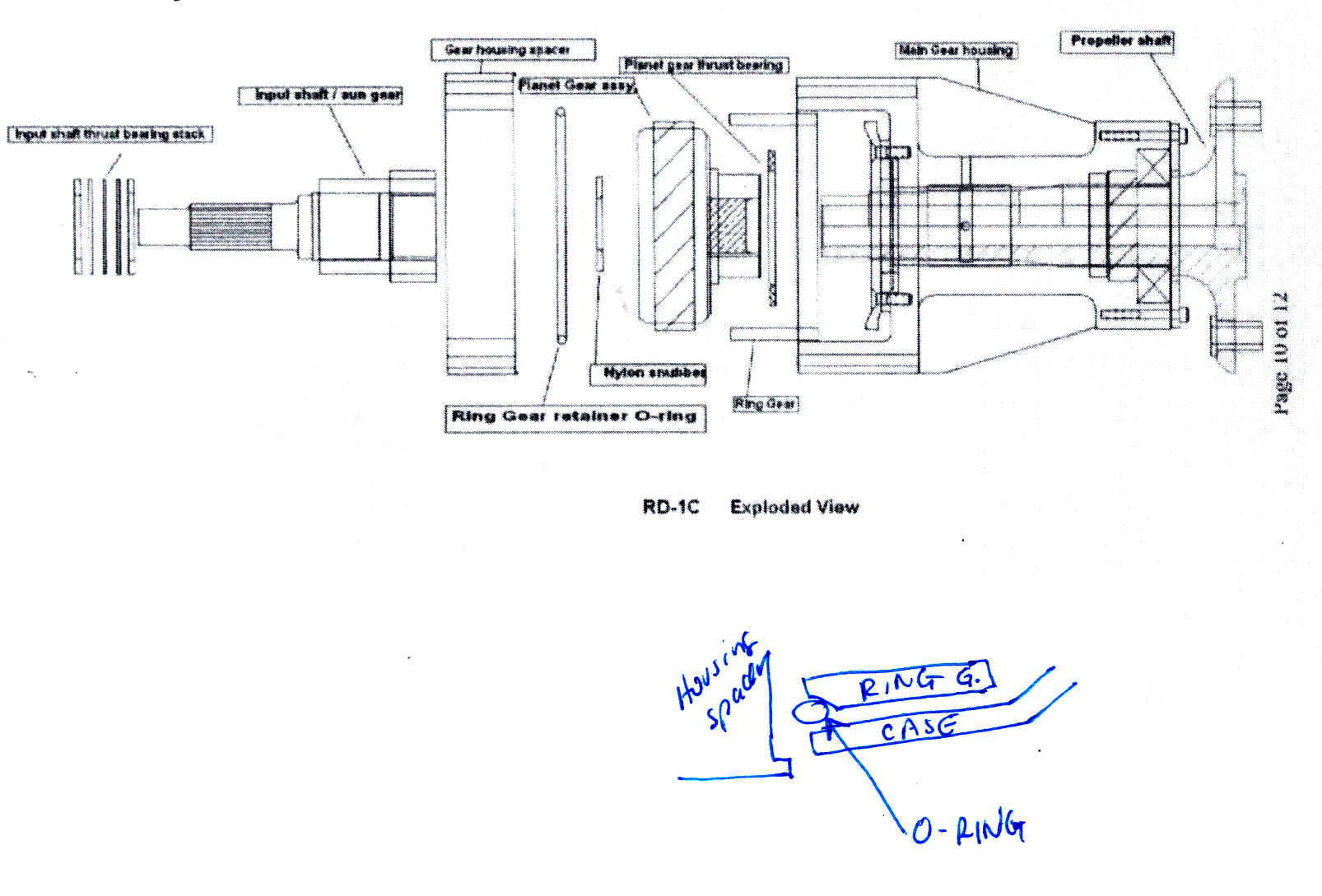
I have attached the expanded view of the RD1-C. The ring gear has a 45 degree cut on the outer circumference to accept the o-ring. The oring just pushes against the solid adapter cylinder (the part that bolts directly to the adapter plate), thus keeping the ring gear tight. It seems this oring spins against one or the other surface when running. So when trial assembling without the oring, the gears spin freely. With the oring in place, there is pressure on the ring gear as the bolts torque down.
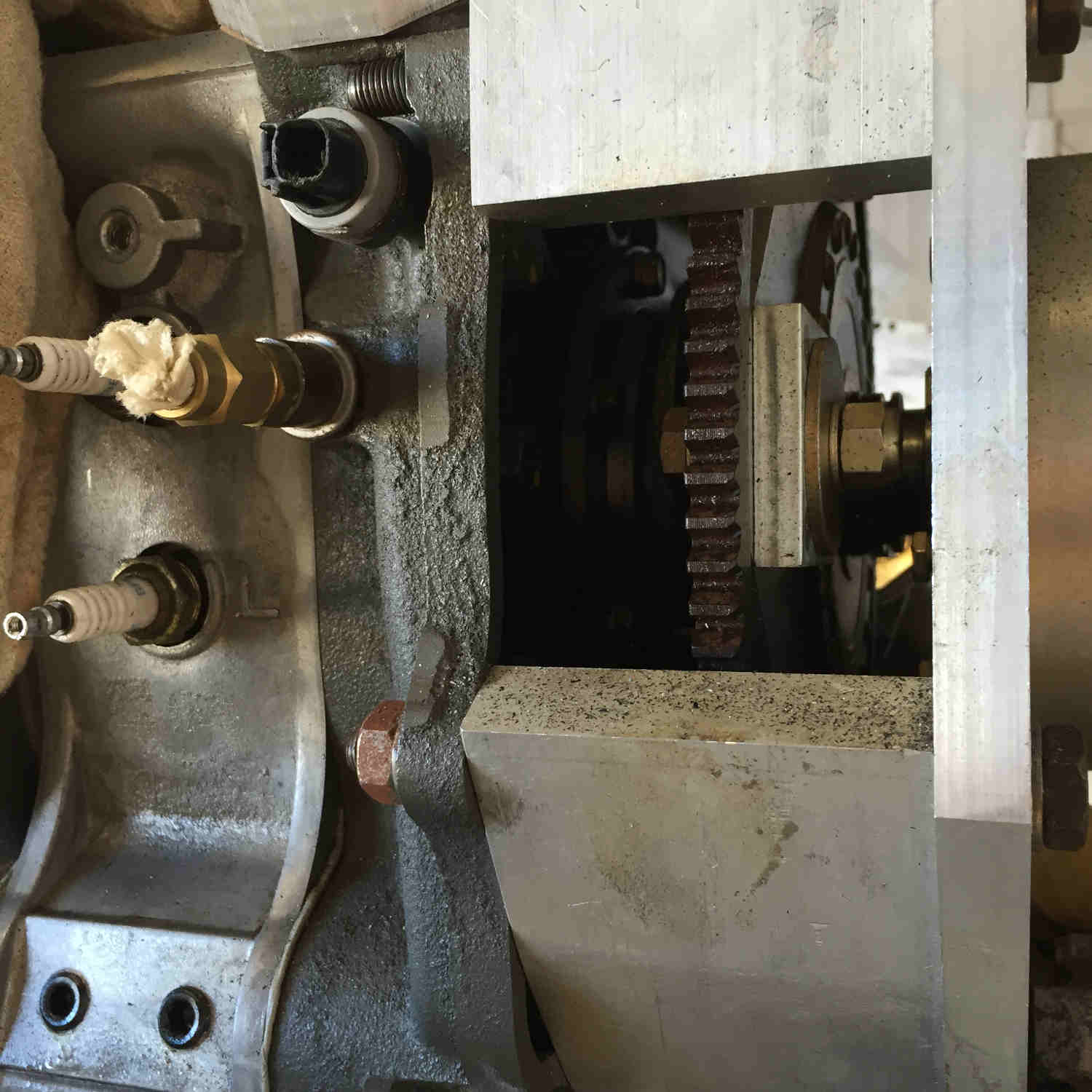
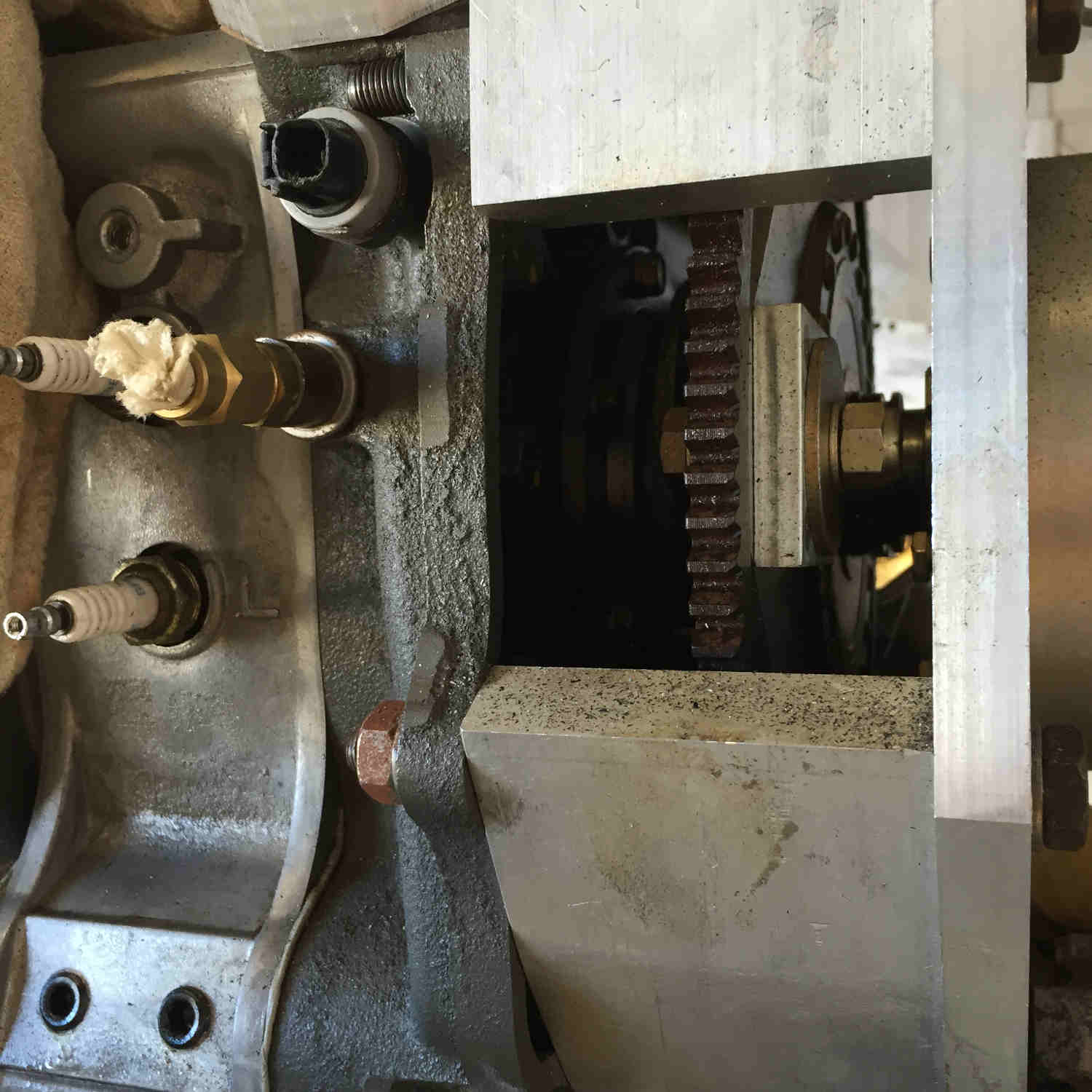
Here is the scan and adapter pix.
Thanks,
Scott Gettings
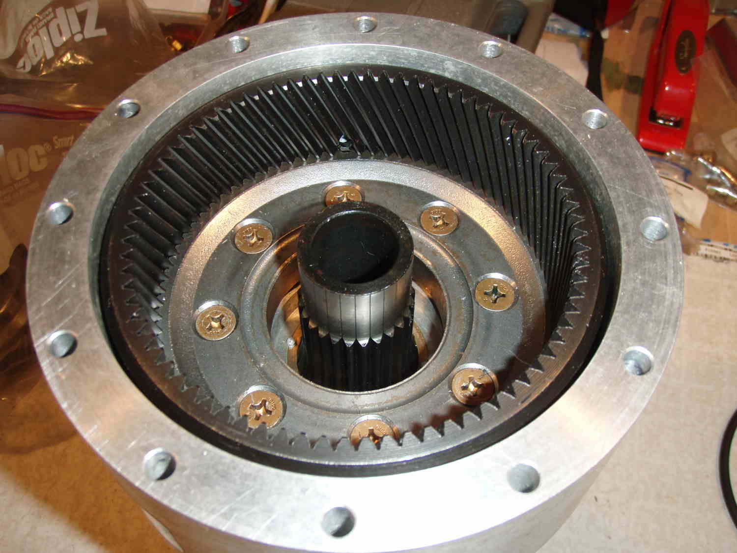
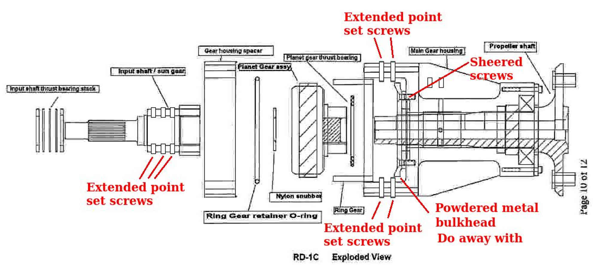
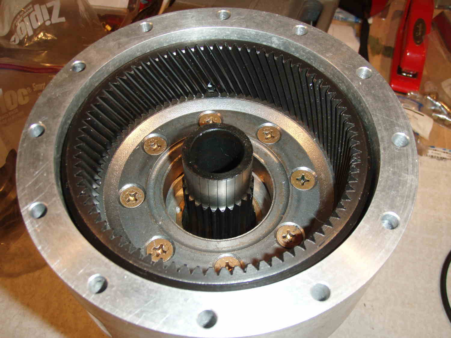
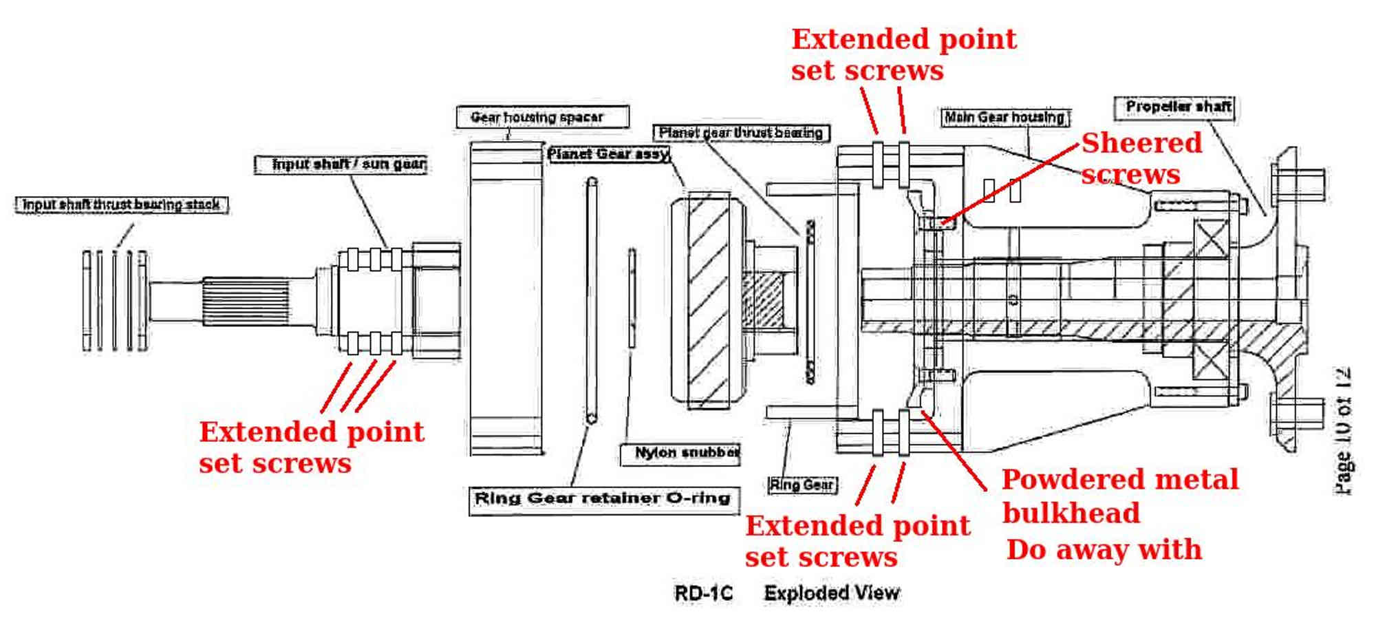
The ring gear is stationary. The bulkhead the ring gear splines on is
bolted to the gear box case. Nothing critical about that O ring.
Those bolts are flat heads screws.
The early ones where known to shear. I think the diameter was increased
in the later versions.
The stock Ford bulkhead is powdered metal and SUPER hard.
Makes a good bolt shear :-)
Old message:
"I found that seven (7) of the eight (8) 1/4-20 bolts holding
the ring gear to the casting were broken. Only one bolt was still in
tact,
and it was loose. After discussing this with Tracy, we agreed to
drill and
tap them to 5/16-20 which I did. "
Please take one of those screws out an measure the diameter for me.
After you fly it for a few hours it disassemble the gear box and check
those bolts
that bolt the ring gear bulkhead to the gear box case.
Paul Lamar
The Rotary Engine free News Letter. Powered by Linux. If you want off
the list PLEASE let me know and I will remove you. ACRE NL web
site.
http://www.rotaryeng.net You Tube
http://tinyurl.com/beqqxas
Copyright 1998-2017 All world wide rights reserved.