David,
Here are all three tach adapters finished machining. Took about 8
hours per adapter.
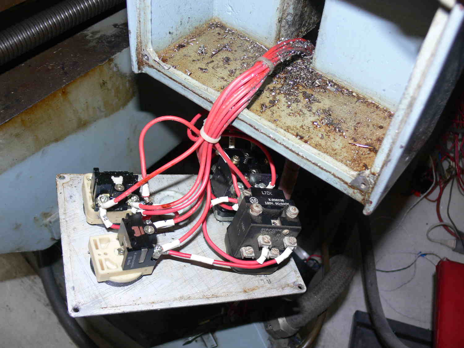
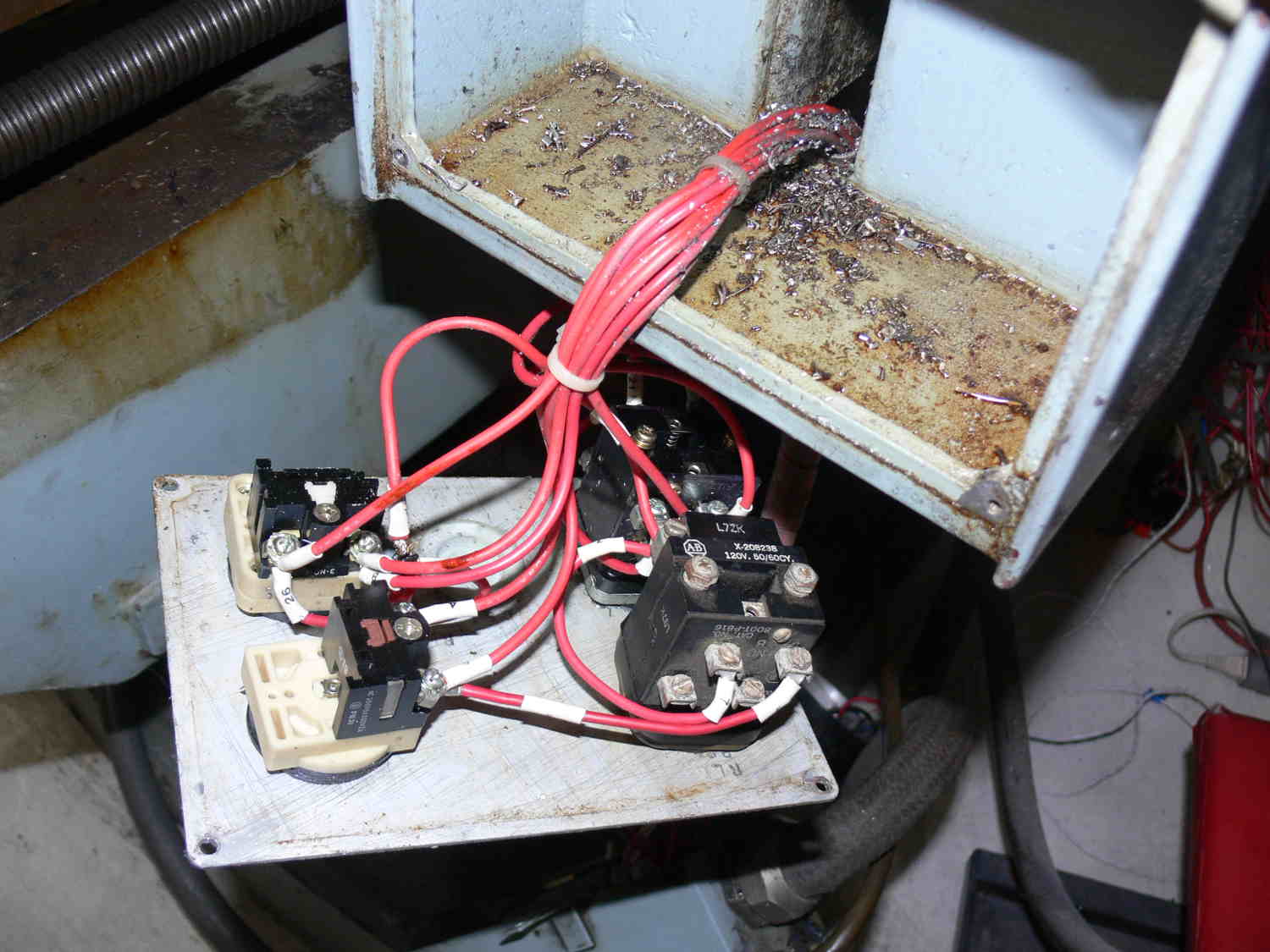
I was rather surprised to see two contactors wired in parallel. It
appears to be the 3 phase for the knee motor. That huge motor can
probably lift 500 or 600 pounds.
I guess back when the Kasuga was built they did not have contactors
with enough current.
"A contactor is an electrically controlled switch used for switching
an electrical power circuit, similar to a relay except with higher
current ratings and a few other differences A contactor is
controlled by a circuit which has a much lower power level than the
switched circuit."
I have a new invention I will upload shortly for simplifying some of
this rat's nest :-)
Paul Lamar
Looks great. I switched to solid state relays, use 5vdc data to
control, no contractors to have carbon Build up or wear out.
David Mikesell San Jose California
Is the idea to turn off all circuits if a limit switch opens some
where?
So all limit switches are in seres? What would the schematic look
like?
I am thinking of a Maxmite and a LED panel that tells you which limit
switch opened.
Or is that feature built in EMC ? Is it in Mach 3 ?
Paul Lamar
You can put all limit switches in a series So if anyone of them
opens it goes into e stop, or if it's in homing it takes that as a
limit to whatever axis was moving. It works that way in mach3 also
EMC. I personally wire each one individually as an individual home
switch and it also acts as a limit switch. And then I use software
driven soft limits while running to make sure I never actually hit
the switch when the machine is moving.
David Mikesell San Jose California
Thanks David
I'll think about that so more.
What is the limit switch voltage?
Paul Lamar
It's a 5vdc logic circuit.
David Mikesell San Jose California
I guess that is the reason some of the Kasuga docs I have recommended
running the limit switch wires in separate conduit. Unfortunately it
was NOT adhered to on this original installation. But I will fix that
and run them in separate conduits.
I am guessing but that would partially explain the dozens of
capacitors used on all the high voltage wires.
Thanks David
Paul Lamar
Paul,
You should also used shielded two strand twisted wire for the limit
switches. You can get false signals from other wires, encoders should
also be shielded to prevent errors.
David Mikesell San Jose California
Personally, I wouldn't connect the limit switches to the E-Stop. It's
hard on drives, plus if your homing the machine to the limit switches,
you're stopping the drives when you do. Limit switches can be configured
to motion stop, or pull power from the drives via software and are then
not hammering the drives from the power side if the switch is hit.
I'd also not recommend contactors (or SSR's) between the drive and
motor, a good way to blow servo drives.
I agree with shielded wiring, limit switches, encoder wiring and your
spindle wiring if it's controlled via vfd.
At least, when I built my mill it's how I did it. Ran very well, never
blew a drive. I ran my wiring in a common cable carrier with ~25' of
cable all running beside each other and no noise issues. I also star
grounded my system, which I think helped with those potential issues also.
Fwiw
Jarrett Johnson
I am not using contractors on the servo drives.
On the spindle motor I am using a Speedcom 3 phase motor controller.
I suspect the EMC software can turn that off depending on the logic.
At least I think so. The limit switches probably feed into the EMC program
and it decides when to stop an axis drive or the spindle motor.
Is that correct David?
So far I have not found that in the EMC docs. Does not mean it is not there.
As I learn these tidbits of info I have to read the EMC docs again
and again so I learn more and more in the process.
I am saving the contactors for the 3 phase knee motor which will not
be tied into the EMC software. It will be strictly controlled
manually. I still need a schematic for that. Either that or a good
book on 3 phase motor wiring.
Jarrett, what software did you use for your NC mill?
Paul Lamar
The limit switches and the e-stop are all independent of each other in
every installation I have done. Most people do them in a series because
it is easier and takes less time and less input pins on the interface
board. Problem is you never know which one is triggered.
I give each one has is own 5vdc signal, and is normally wired NC so that
a limit is hit, or switch failure, even if a connector or wire break it
stops the mill. With each one wired independent you will get a flag
indicating which system that trigger the event.
I do not use contactors or SSR's between drives and motors. I was just
telling Paul I do not use contactors for anything. I use SSRs for
turning on coolant pumps, actuators for tool changers. This way you can
use the standard 5vdc logic signal and the ssr triggers and lets what
ever voltage ac or dc you are using to do its job. No transformers for
worrying about voltage spikes to the control interface or line noise.
Yes Paul, when we set up the multi-function board, there are numerous
inputs just for signals. In EMC we will tell it what each pin is
assigned to and whether it is in a pull up or pull down condition
normally. That way any change from that state is registered and causes
the action we want.
It really is pretty easy, especially someone with your background. The
real trick is learning when reading these manuals on controllers and
software to realize what is really pertinent to your particular
installation.
When I come down and we do this, in the end you will feel like kicking
yourself because it will go pretty fast and easy during the software
setup. the hardest part is doing the motor tuning to set the speed,
torque and revolutions per inch.
David Mikesell
San Jose, CA
So shall I replace the knee contactors with solid state switches?
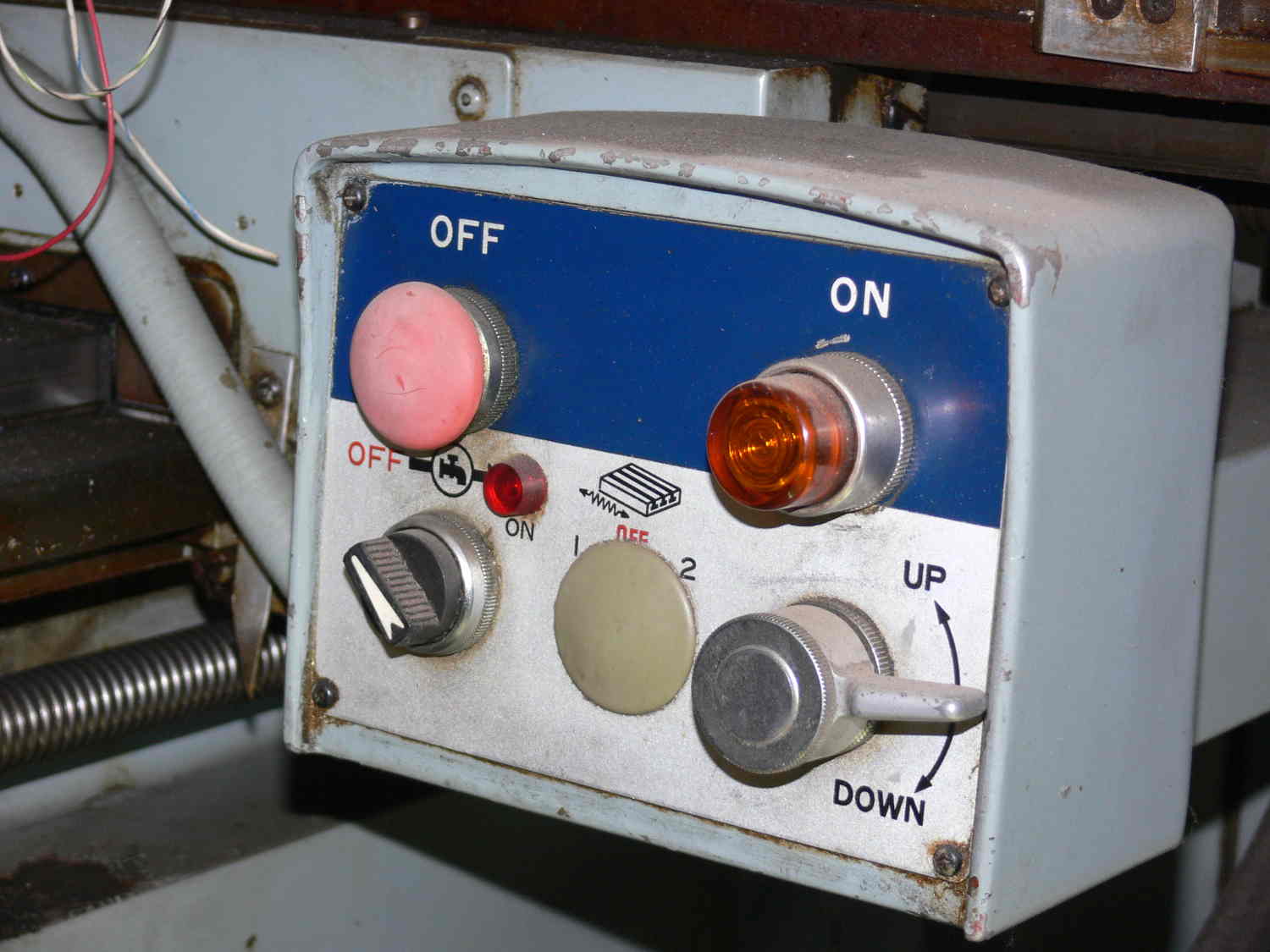
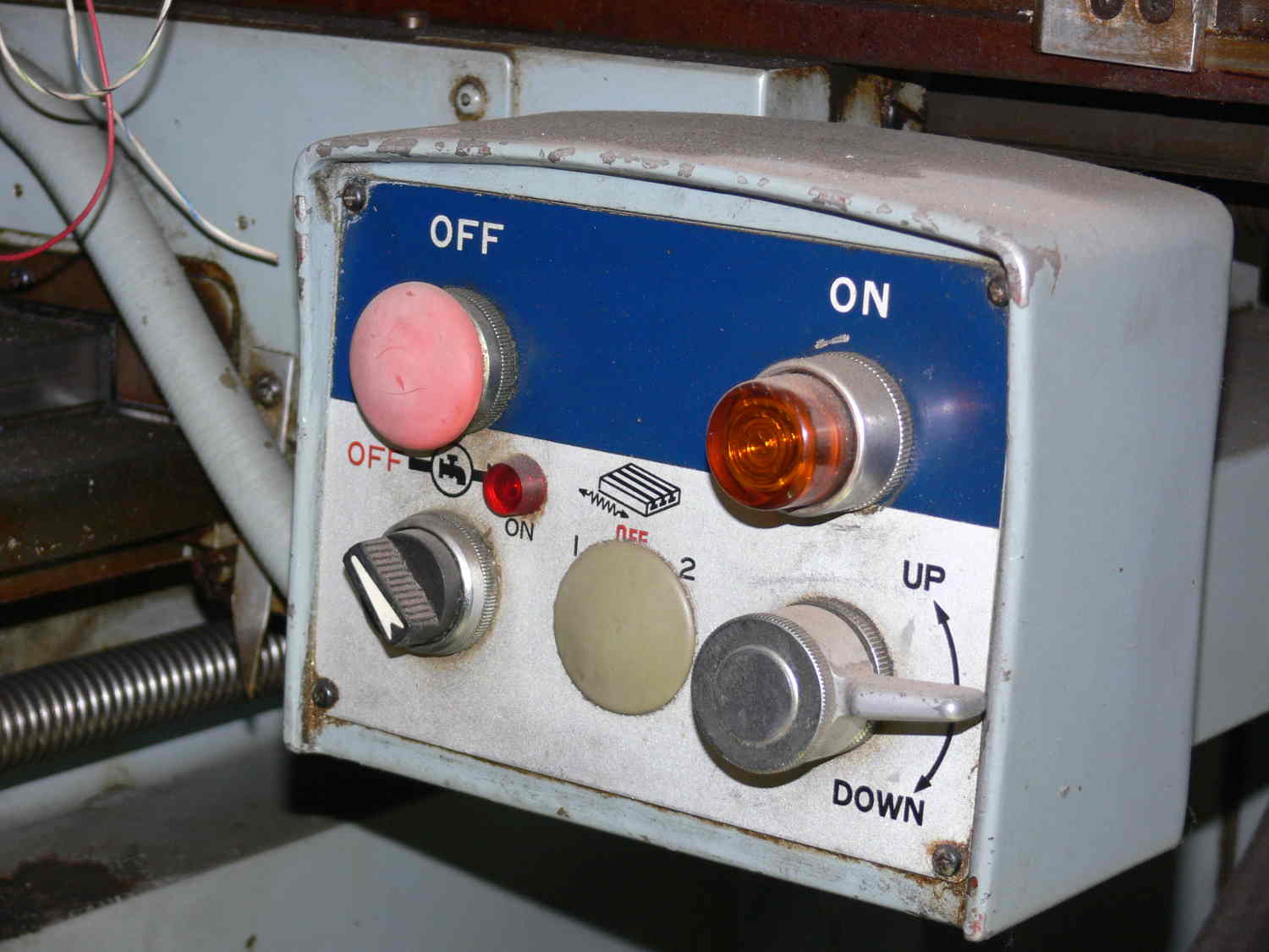
Can I control them with that switch box?
I love the idea of the 5 volt logic and doing away with all that
dangerous 110 Volt switching.
Do you have a schematic or do I need to program a Maximite to do it.
I assume I need at least two of these to reverse the motor?
Still no need or intention to control it with EMC. I only need to set
the knee height once per part type.
Paul Lamar
Well Paul, we can also set it up as another axis and you can come and
from AMC War from within your G-Code running while running apart. Or we
can use manual switches the way it's set up now.
I need to see it and store a schematic of how it's set up now to decide
the best way to run it
David MikesellSan Jose California
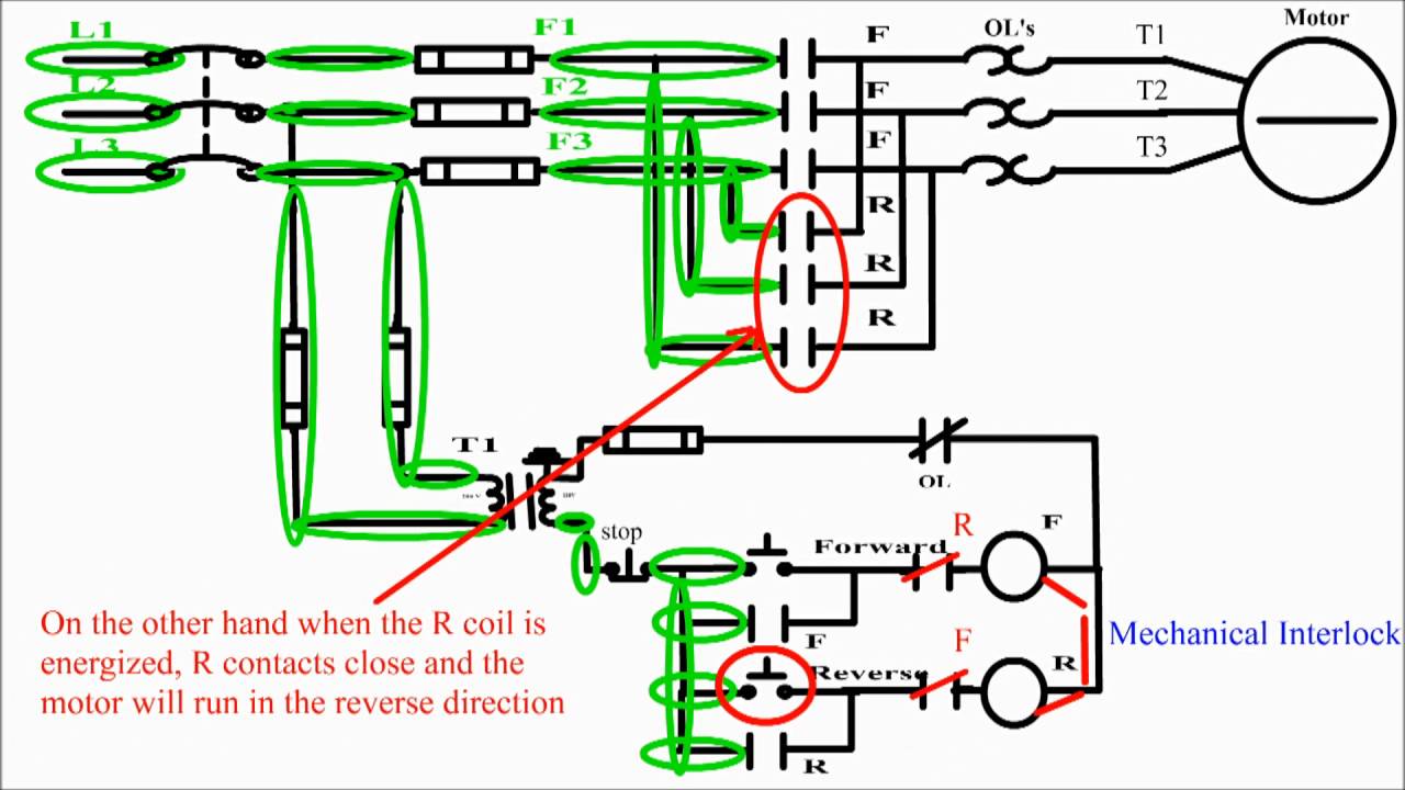
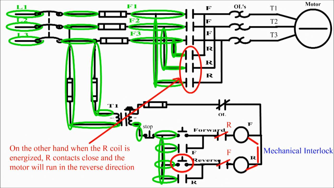
To make a schematic of what I have is really tough.
Basically what it is doing is controlling the contactors by switching
110 volt coils on an off.
Motor on motor off. Motor up motor down. That's it.
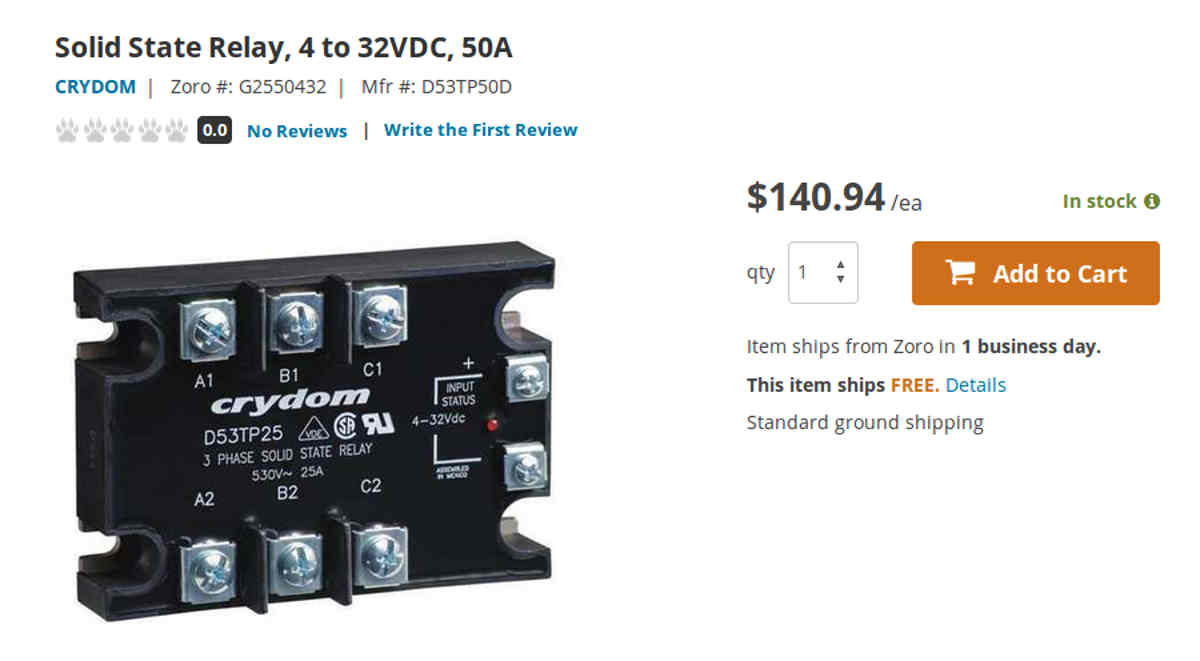
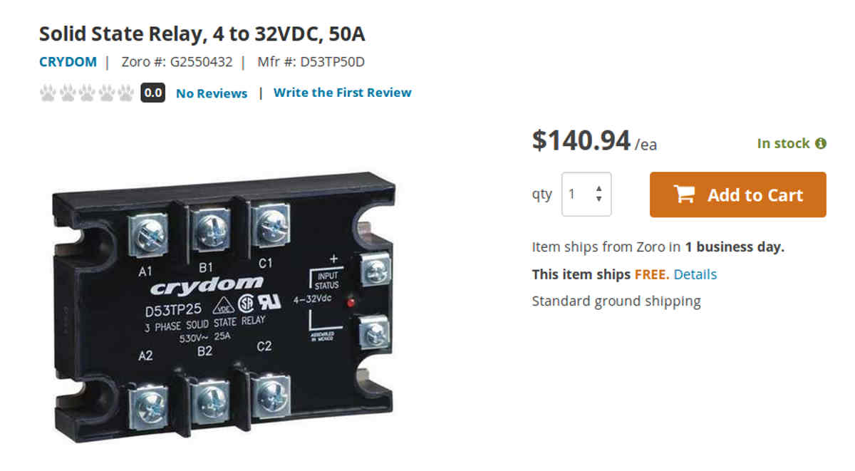
Can I do it with just two 3 phase SS switches.
Keep it simple. No need to get it into EMC.
If you have a suggested schematic for the switching I can wire it up and
test it
before you get here.
Are those 3 phase solid state switches OK?
I think one big solid state switch could do all the 3 phase motor direction
change and perhaps speed in one large piece of silicon :-)
Paul Lamar
The Rotary Engine free News Letter. Powered by Linux. If you want off
the list PLEASE let me know and I will remove you. ACRE NL web
site.
http://www.rotaryeng.net You Tube
http://tinyurl.com/beqqxas
Copyright 1998-2017 All world wide rights reserved.