David,
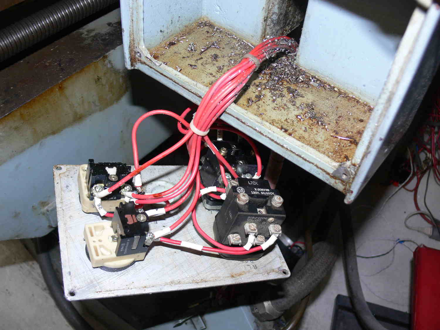
I was rather surprised to see two contactors wired in parallel. It
appears to be the 3 phase for the knee motor. That huge motor can
probably lift 500 or 600 pounds.
I guess back when the Kasuga was built they did not have contactors
with enough current.
"A contactor is an electrically controlled switch used for switching
an electrical power circuit, similar to a relay except with higher
current ratings and a few other differences A contactor is
controlled by a circuit which has a much lower power level than the
switched circuit."
Paul Lamar
Looks great. I switched to solid state relays, use 5vdc data to
control, no contractors to have carbon Build up or wear out.
David Mikesell San Jose California
Thanks David
Paul Lamar
Paul,
I am saving the contactors for the 3 phase knee motor which will not
be tied into the EMC software. It will be strictly controlled
manually. I still need a schematic for that. Either that or a good
book on 3 phase motor wiring.
Paul Lamar
I do not use contactors or SSR's between drives and motors. I was just
telling Paul I do not use contactors for anything. I use SSRs for
turning on coolant pumps, actuators for tool changers. This way you can
use the standard 5vdc logic signal and the ssr triggers and lets what
ever voltage ac or dc you are using to do its job. No transformers for
worrying about voltage spikes to the control interface or line noise.
It really is pretty easy, especially someone with your background. The
real trick is learning when reading these manuals on controllers and
software to realize what is really pertinent to your particular
installation.
When I come down and we do this, in the end you will feel like kicking
yourself because it will go pretty fast and easy during the software
setup. the hardest part is doing the motor tuning to set the speed,
torque and revolutions per inch.
David Mikesell
San Jose, CA
So shall I replace the knee contactors with solid state switches?
Can I control them with that switch box?
I love the idea of the 5 volt logic and doing away with all that
dangerous 110 Volt switching.
Do you have a schematic or do I need to program a Maximite to do it.
I assume I need at least two of these to reverse the motor?
Still no need or intention to control it with EMC. I only need to set
the knee height once per part type.
Paul Lamar
Well Paul, we can also set it up as another axis and you can come and
from AMC War from within your G-Code running while running apart. Or we
can use manual switches the way it's set up now.
I need to see it and store a schematic of how it's set up now to decide
the best way to run it
David MikesellSan Jose California
To make a schematic of what I have is really tough.
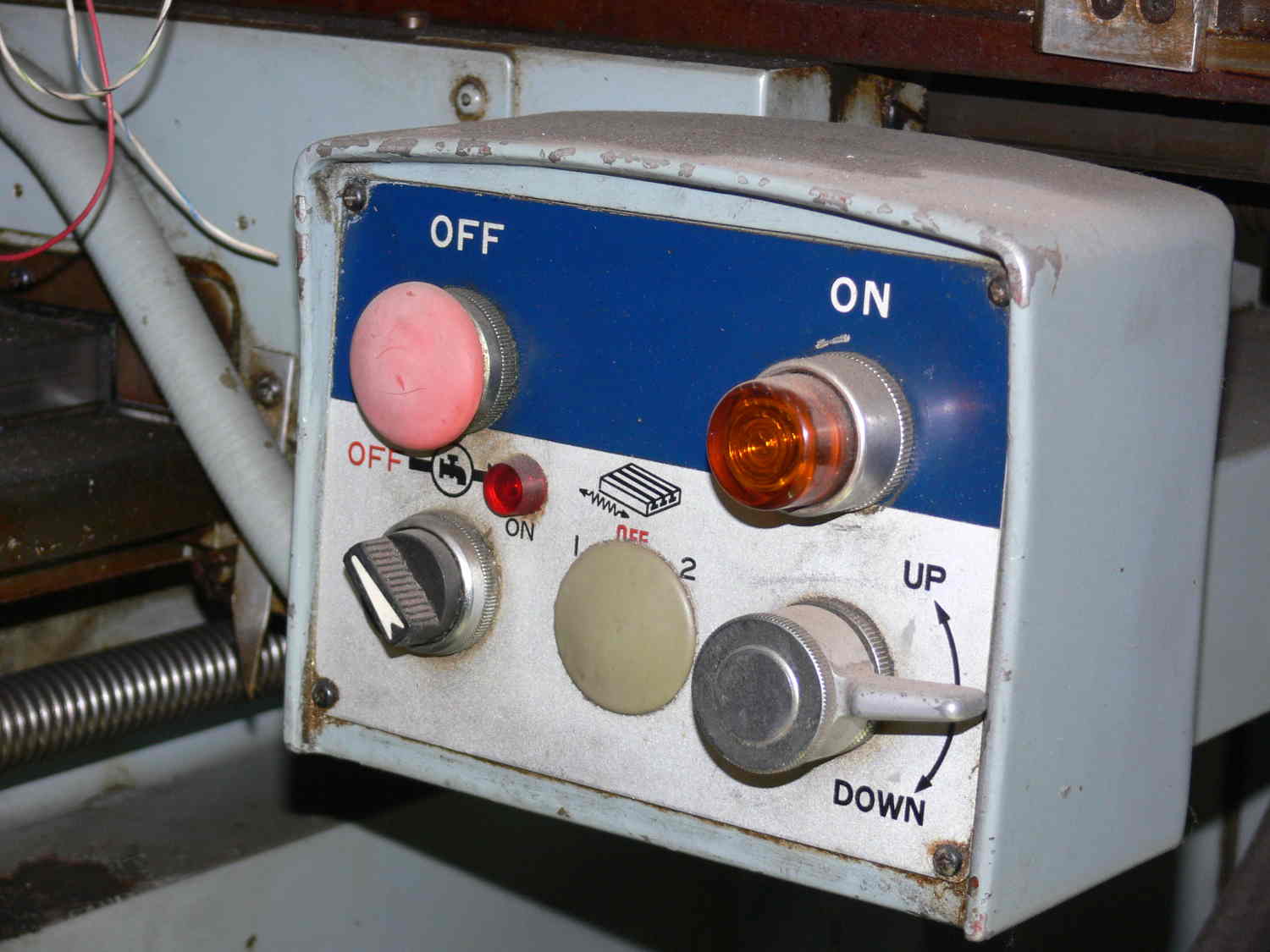
Basically what it is doing is controlling the contactors by switching
110 volt coils on an off.
Motor on motor off. Motor up motor down. That's it.
Can I do it with just two 3 phase SS switches.
Keep it simple. No need to get it into EMC.
If you have a suggested schematic for the switching I can wire it
up and test it before you get here.
Are those 3 phase solid state switches OK?
I think one big solid state switch could do all the 3 phase motor
direction
change and perhaps speed in one large piece of silicon :-)
Paul Lamar
Yes Paul you.can. The picture you sent, the cryodon, are the same ones I
use. Never had a failure yet. Yes.they will.directly replace.the old
contactor relays.
David Mikesell
San Jose California
I think this is a good way of doing it.
Four single throw SS switches.
To turn the motor off I think all I have to do is turn off the five volt
supply. I'll use three big fuses in the 3 phase supply.
How many amps would you guess the knee motor to be?
Paul Lamar
Hi Paul
To go with single or three phase solid state relays you will need to
include more control elements to protect the motors and relays.
You will need run down and direction change delays.
3 Phase motors don't like instantaneous direction changes and I suspect
the solid state relays may also suffer.
There were no attachments with the previous mail but I see them on later
ones.
Your machine does not have a control transformer or low voltage control
circuitry on the Knee motor control so the majority of the schematic is
irrelevant.
The main contactor does not have a self hold contact so it would be
controlled by a simple on off switch or a separate relay not in the
picture. once the main contactor is energised the raise / lower switch
on the control panel would provide all the control delays necessary due
to the internal switching architecture
-----------------------------------------------------------------------------------------
Sorry I missed the previous post.
There is no reason you could not use the existing switch panel and a
couple of IO to control solid state relays.
Maybe just a little bit superfluous.
Regards
Bill McDonald
As I understand all I have to do is swap two of the phases to reverse
the motor.
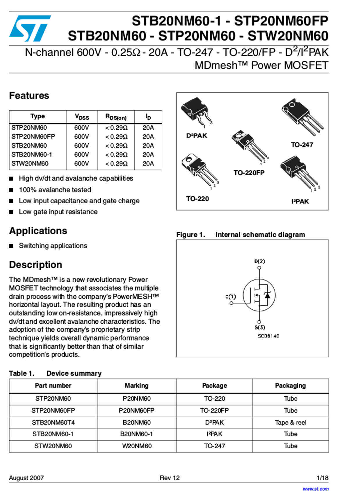
I will try to build my own SS Switches using these $6 MOSFET. An off the
shelf SS Switch
is about $40 each and I need 4 for a total cost of $120. I will need 8
of the MOSFETs
I think. Two back to back for each channel so total cost is $48 plus
what ever the PC board cost.
These are 600 V 20 Amps and I probably can get away with cheaper 300 V
versions.
Lots of progress has been made in these devices in the past few years.
I'll build a test rig in the next few days.
Paul Lamar
The Rotary Engine free News Letter. Powered by Linux. If you want off
the list PLEASE let me know and I will remove you. ACRE NL web
site.
http://www.rotaryeng.net You Tube
http://tinyurl.com/beqqxas
Copyright 1998-2017 All world wide rights reserved.