Hi Paul;
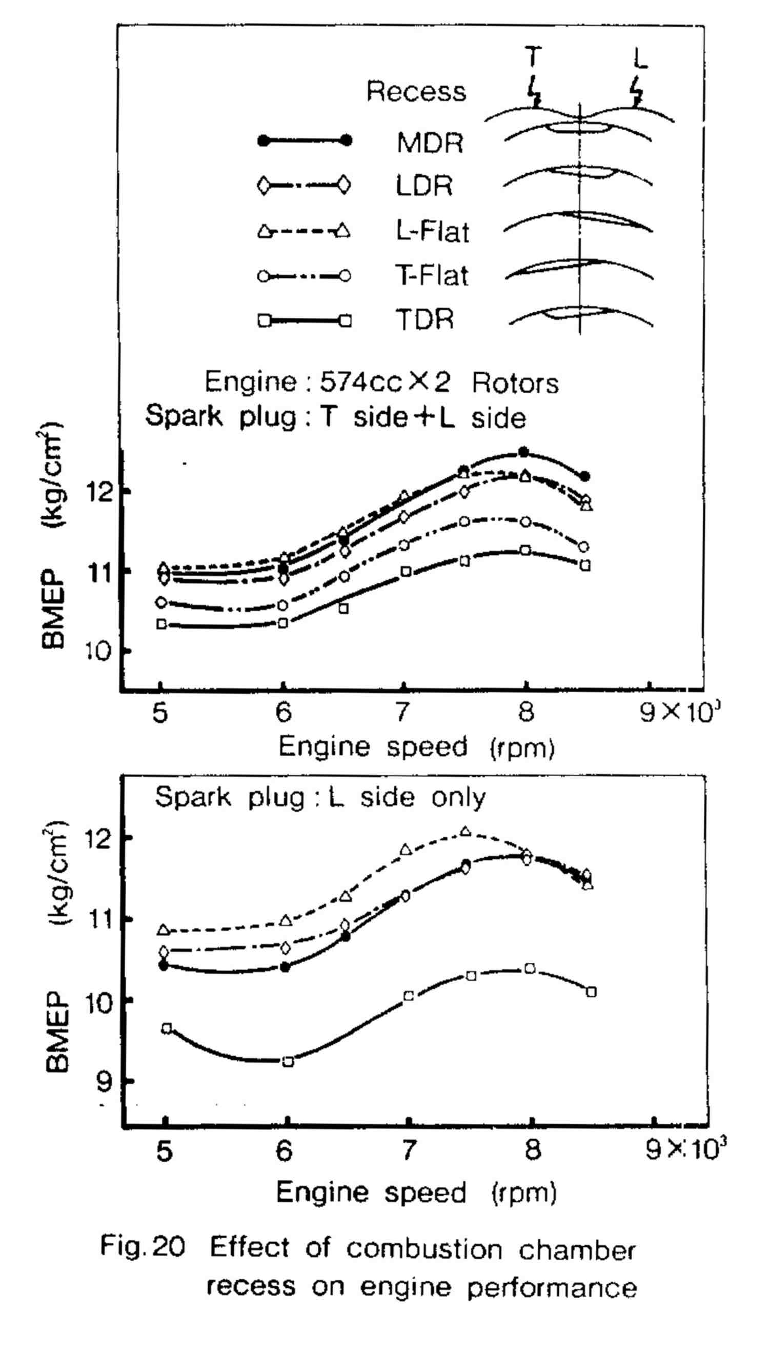
If you're looking at doing rotor & efficiency mods - Take another
look at the SAE841017 - recent 84 tech pg 6, Fig 14,13,20, note
very low BSFC @ 7500rpm in fig.14 for the large pport. And the
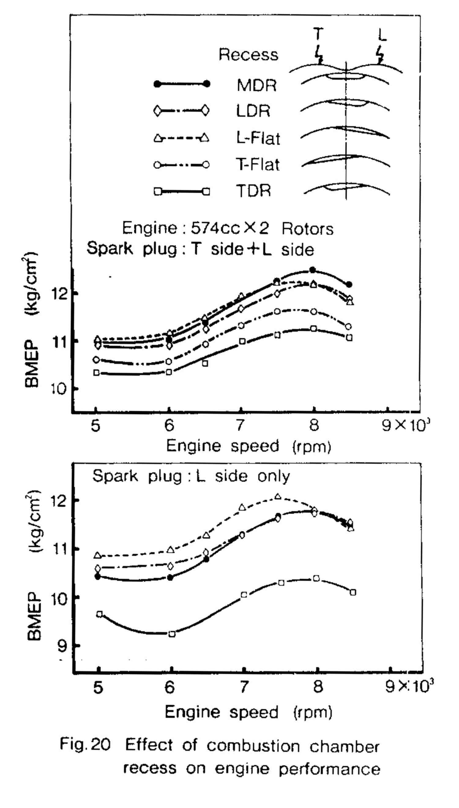
81RE-KY bible p.48-49-53 LDR/MDR/L-flat charts for BSFC/MEP
improvements.
Cheers Cary Beazley
The 81RE-Ken Yamamoto bible p.48-49-53 LDR/MDR/L-flat charts for
BSFC/MEP
improvements are within the margin of measurement error IMHO. Notice
the RX 8 used neither :-) The bathtub is symmetrical and wider.
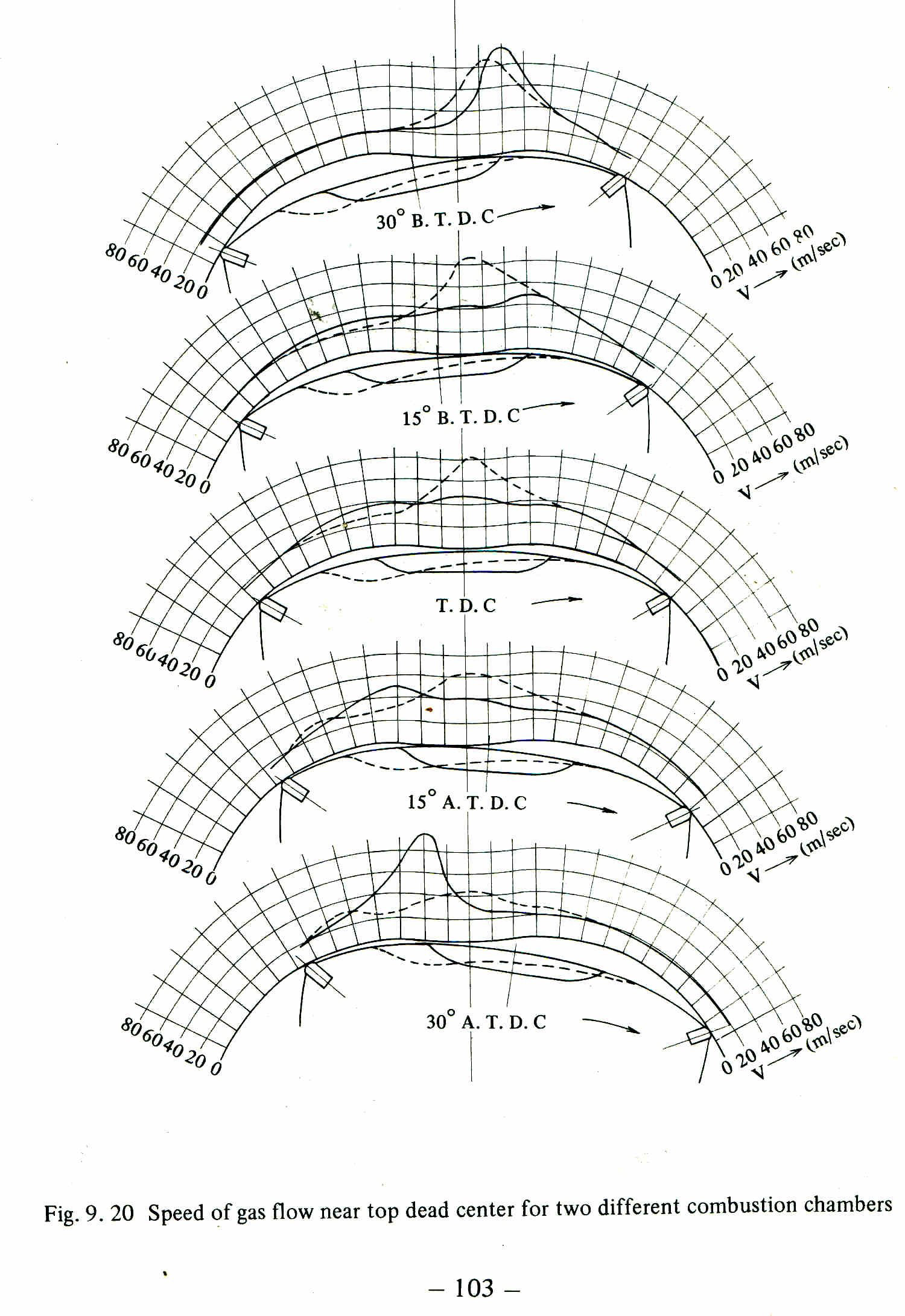
Here is the combust data out of the 84 paper.
It implies there is a difference in pressure at the spark plug
holes !!!!!!!
If the pressure is not equal the force vector is deflected.
More data is needed with more pressure sensors. One every 1/4 inch or
even 1 every 1/2 inch.
More work needs to be done on the bath tubs.
And the wind problem.
Paul Lamar
Yep, may very well be measurement or calibration error - definitely a
difference between the the 81 bible and 84 tech papers, & CW papers.
Fully agree on the need for more research and maybe see the latest
direct injection and ignition research.
I would argue the rx8 side port configuration might have been chosen
more to reduce emissions with more focus on low-mid power drive-ability.
I'm still looking for an old chart showing the BSFC/BMEP due to side
port turbulence swirl.
Cary Beazley
Well I got my Rhino up and running and drew some rotors.
I was amazed again at a small difference in the location of the center
of the pressure
vector relative to the center of the rotor surface made so much
difference in
the torque generated.
One reason for this is the extremely short stroke of the e-shaft.
If the center of pressure is off by as little as an inch a large
difference in the amount of torque generated when the e-shaft
is 90 degrees beyond TDC and the rotor has rotated 30 degrees.
There is also a torque on the rotor about it's center reacted by the
stationary gear.
The e-shaft moment arm drastically changes.
The very best configuration is move the center of pressure as
far upstream or aft as you far as you can get it.
Given the geometry it is amazing
the Wankel is so close to the piston engine.
Paul Lamar
Hi!: thanks for the very good image 'breakthrough..', that I don't catch
in full, but a doubt comes to my mind, if the space above the Rotor
surface is continuous, i.e, having no walls, pressure applied to rotor
surface must have no major differences from leading area to training
side, as the pressure is transmitted uniformly through a gas.
Are there any experimental measurements in the line of local pressure
and torque to shaft differences according to recess type?
Thanks, regards, Salut �
Jose Gros-Aymerich
Madrid, Spain
That is not true when there is motion involved. Just like an airplane flying
in a large sealed hangar. In this case there is dynamic pressure in front
of the advancing trailing apex seal. When the top surface of the rotor
approaches
the inner surface of the rotor housing, at high speed, a strong airflow
is generated and moves forward increase the air pressure in the leading
part of the moving combustion chamber.
Since the air velocities involved are quite high at about 200 MPH the
dynamic pressure
can be as much as 100 pounds per square foot or .7 psi. Perhaps more.
Thanks for bring that up. It is called dynamic pressure.
Paul Lamar
The Rotary Engine free News Letter. Powered by Linux. If you want off
the list PLEASE let me know and I will remove you. ACRE NL web
site.
http://www.rotaryeng.net You Tube
http://tinyurl.com/beqqxas
Copyright 1998-2017 All world wide rights reserved.