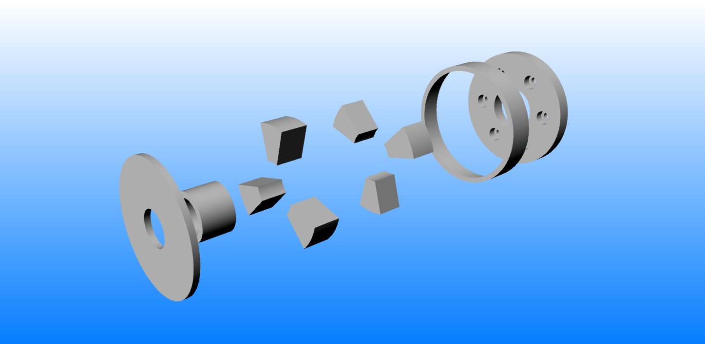
I have an idea for you Scott.
There is a water jet company in 1500 Airway Circle, New Smyrna Beach
FL. 32168 | 386-424-7333
http://www.advmach.com/waterjetcutting.html
Water Jet Cutting at Advanced Machining in New Smyrna ...
www.advmach.com
Water Jet Cutting at Advanced Machining in New Smyrna Beach Florida.
Waterjets are perfect for creating everything from corporate logos to
the top quality parts you ...
I have some drawings of a steel coupling that can be made out of
water jet cut steel parts.
Then you will need to find a local tig welder to weld it up.
I have some of the parts. The inner plate that bolts to the counter
weight and the outer ring cut from six inch tubing.
$50 plus mailing.
Use part of Tracy's torque isolator to adapt this to Tracy's PSRU
input shaft. Drill out the rivets and bolt it to the steel output
front plate.
Paul Lamar
Very interesting! I can query the water jet shop, and will order these
parts if the shop can make the rest. No problem with the welder.
How thick is the metal?
Do you intend for an outer ring to be cut into the small curved shapes,
or make these from scratch? I guess they can be flat instead of curved?
I also assume the 1.78” is the height of each component, so the total
thickness would be about 2”? I will study my redrive to look for areas
of potential interference.
Please ignore the curved questions of my last post, sorry. Some of the
latter images didn’t display the first time. I see the connecting
elements are square.
Thanks!
Scott Gettings
.050 to .150. Some of the stuff is .083. You make it out of what you
can find :-)
The six inch tubing is about .150 wall.
The total thickness is about 1.8 inches. Nothing about this is critical.
One inches
would work if your not shooting for 500 HP.
Ignore those square pictures. The latest are triangular or wedge shaped.
The square ones bottom out corner to corner. We discovered that when
we built the TTC coupling.
If I get a little more interest in this I wall make a tool that bends
the wedges in
a hydraulic press. Saves a bit of welding. I have built tools like that
in the past.
That would pay off as the same design can be used in new gear boxes.
We already used one of these that was similar in a 3 rotor.
I have not heard back from Kevin so if Kevin finds
an NC shop that can make them out of billet at reasonable cost
that would be more accurate.
In any event once this is welded up it would be wise to balance it between
parallel bars. If your gear box is off the engine please tell me the
diameter
of the input spline adapter Tracy is using. The one with all the rivets.
That will control the diameter of the forward plate.
Paul Lamar
Paul
Can i make you a suggestion, you can made it from an aluminum block and
water pressure cut all contour for the outer profile without back plate
and the part left cut the inner part, then you do have to cut the front
plate and back plate with holes reassemble with tig welding, it will be
much more simple. if you have distortion from welding just resurface the
front and back plate on lathe or milling machine and balance
JEAN PRUDHOMME
I think I understand what you are suggesting.
Cut the six wedges out of thick aluminum plate or bar ( say on a band
saw). Bolt or tig weld them
to a six inch diameter aluminum tube for the front half. For the back
half bolt or tig
weld them to an aluminum plate.
That will work.
Here is a 3D. All you need is a band saw and lathe.
Great idea Jean. Thanks.
Paul Lamar
The Rotary Engine free News Letter. Powered by Linux. If you want off
the list PLEASE let me know and I will remove you. ACRE NL web
site.
http://www.rotaryeng.net You Tube
http://tinyurl.com/beqqxas
Copyright 1998-2017 All world wide rights reserved.