I have an idea for you Scott.
There is a water jet company in 1500 Airway Circle, New Smyrna Beach
FL. 32168 | 386-424-7333
<tel:386-424-7333>
http://www.advmach.com/waterjetcutting.html
<http://www.advmach.com/waterjetcutting.html> I have some drawings of a
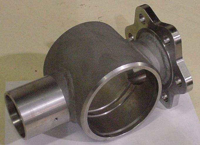
steel coupling that can be made out of
water jet cut steel parts.
Then you will need to find a local tig welder to weld it up.
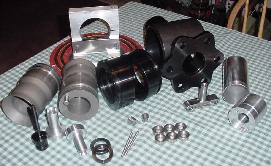
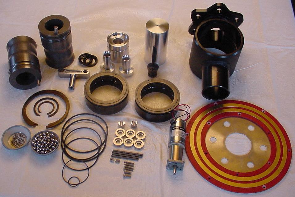
I have some of the parts. The inner plate that bolts to the counter
weight and the outer ring cut from six inch tubing.
$50 plus mailing.
Use part of Tracy's torque isolator to adapt this to Tracy's PSRU
input shaft. Drill out the rivets and bolt it to the steel output
front plate.
Paul Lamar
Very interesting! I can query the water jet shop, and will order
these parts if the shop can make the rest. No problem with the
welder.
How thick is the metal?
Do you intend for an outer ring to be cut into the small curved
shapes, or make these from scratch? I guess they can be flat
instead of curved?
I also assume the 1.78” is the height of each component, so the total
thickness would be about 2”? I will study my redrive to look for
areas of potential interference.
Please ignore the curved questions of my last post, sorry. Some of
the latter images didn’t display the first time. I see the
connecting elements are square.
Thanks!
Scott Gettings
.050 to .150. Some of the stuff is .083. You make it out of what you
can find :-) The six inch tubing is about .150 wall.
The total thickness is about 1.8 inches. Nothing about this is
critical. One inches would work if your not shooting for 500 HP.
Ignore those square pictures. The latest are triangular or wedge
shaped. The square ones bottom out corner to corner. We discovered
that when we built the TTC coupling.
If I get a little more interest in this I wall make a tool that bends
the wedges in a hydraulic press. Saves a bit of welding. I have built
tools like that in the past. That would pay off as the same design
can be used in new gear boxes. We already used one of these that was
similar in a 3 rotor.
I have not heard back from Kevin so if Kevin finds an NC shop that
can make them out of billet at reasonable cost that would be more
accurate.
In any event once this is welded up it would be wise to balance it
between parallel bars. If your gear box is off the engine please tell
me the diameter of the input spline adapter Tracy is using. The one
with all the rivets. That will control the diameter of the forward
plate.
Paul Lamar
Paul,
My welder can assemble these small steel parts, but is not highly
confident of the precise alignment and balance of the end product. It
looks like some other options are evolving, so I’ll keep this one on hold.
My gearbox is on the engine, but if you need the exact shaft diameter
soon, I will be happy to pull the it and measure the shaft.
Other measurements that might be helpful:
distance from front edge of flex plate gear to rear of engine block: 1
5/16”
distance from front of Tracy’s adapter plate to engine block (the total
“open” area between the engine and adapter): 3 1/8”
distance from front of Tracy’s adapter plate to rear face of his riveted
spline adapter: 1 1/4”
the front of the spline adapter appears very close to the rear edge of
the flex plate ring gear.
It appears that the total thickness of a new coupler (for Tracy’s RD)
would need to be the exact distance from the rear face of the bolted
area of the flex plate to the rear of its ring gear, which is the plane
of the front of the riveted part of the spline adapter. This would
maintain the dimensions for the thrust bearings. A coupler that is more
thick than this would move the rest of the RD to the rear, requiring
alteration of the existing spacers (the 3 1/8” distance). A thinner
coupler could be managed with thrust bearing washers.
Scott Gettings
I just happened to have one.
The OD of the part in question is 6.188. The long part that sticks away from
the engine 1.158 long.
The idea is to turn it around and put the long part inside the coupling.
We worked this out years ago :-) 3D's 5 and six show this config.
That Ford part raw weighs 3 pounds. There is unnecessary meat on
both sides that I can be cut off if you send me yours. That will give you
plenty of room and save a bit of weight. Some of the spline part can be
cut off as well. 1.25 inches of spline would be plenty.
Jean is down the road from you in Pompano Beach and he might do
it for you. He has a lathe and a mill. He will need one sooner or later :-)
Here are a few pictures.
Paul Lamar
Paul how is the reliability on the auto trans style planetary type psru
like you guys are running, are there a few out there with some time on
them? I would think it's better than the gear and idler set up there
running on ls1 motors and stuff. It's not a problem cause the rotary
engine profile is so small but for a v8 or something unless it was
inverted the crank center line is probably too low for most airframes.
Most auto conversions seem to have a lot of gearbox problems, the design
you guys are using seems pretty solid. Have you seen anyone make one
with a constant speed hub?
Thanks, Jacob Sturges
Been used since 1973. Ford has beefed it up over the years. Started with
3 pinions now up to six. Used on the Power Stroke diesel in heavy duty
pick up trucks.
Paul Lamar
Paul how is the reliability on the auto trans style planetary type psru
like you guys are running, are there a few out there with some time on
them? I would think it's better than the gear and idler set up there
running on ls1 motors and stuff. It's not a problem cause the rotary
engine profile is so small but for a v8 or something unless it was
inverted the crank center line is probably too low for most airframes.
Most auto conversions seem to have a lot of gearbox problems, the design
you guys are using seems pretty solid. Have you seen anyone make one
with a constant speed hub?
Thanks, Jacob Sturges
I would say well over a hundred have flown with another 100 in the works.
One guy on a gyro had over 2600 hours in flight training service.
Many people have well over 1000 hours.
Paul Lamar
Paul, I saw pictures a while back of 3 ear damper of aluminum. which
would be better than the steel weld together parts or the aluminum unit
I saw in the picture?
James Whitehurst
Are you getting all the pictures. If in doubt send back the picture in
question.
I think you are referring to the NC milled version.
There are three at latest could. One made from steel parts. One made
from a bunch of aluminum parts. And one made from solid aluminum on
an NC mill. It is mostly a question of cost.
Paul Lamar
Sounds good, has anyone done or thinking about doing one with a constant
speed hub. With a turbo rotary, I think a constant speed will benefit
everywhere if your planing on using the plane at high altitudes and want
max performance in climb, altitude, and cruise, which I am.
Thanks, Jacob Sturges
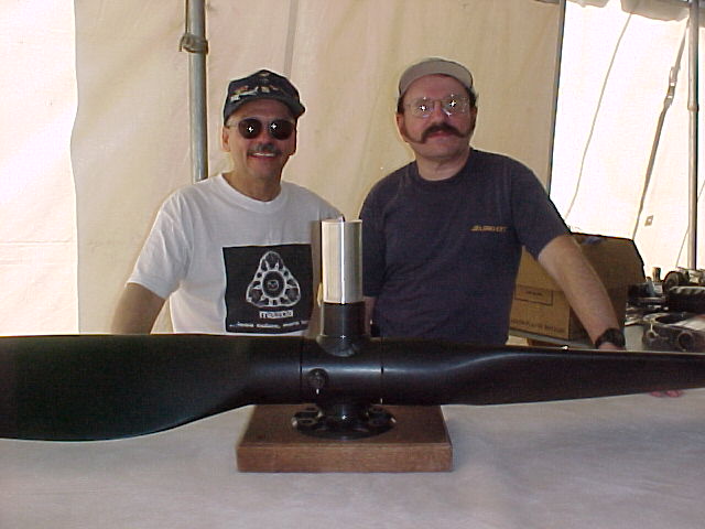
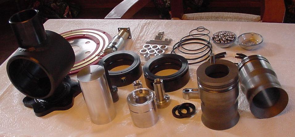
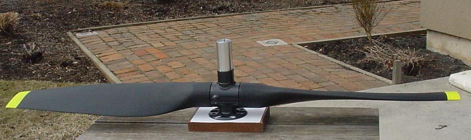
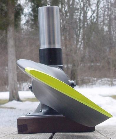
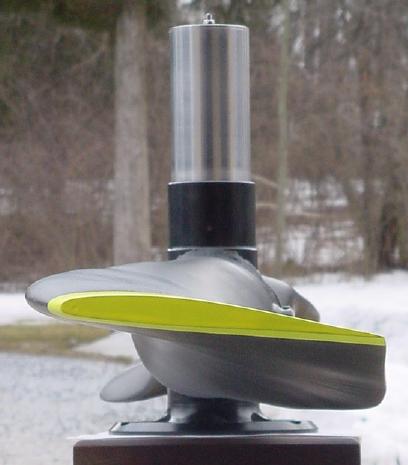
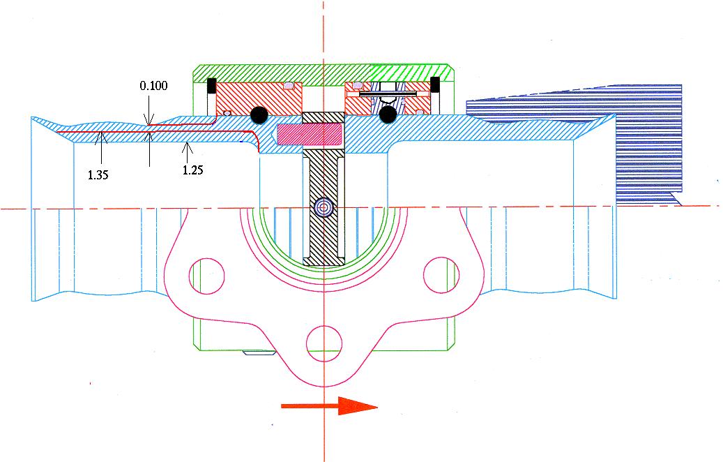
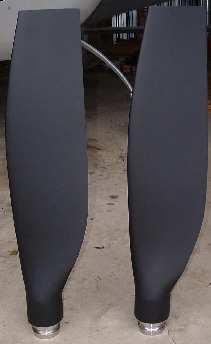
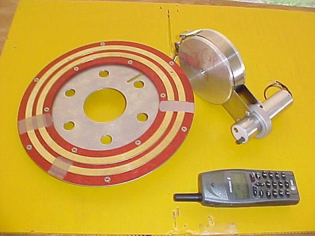
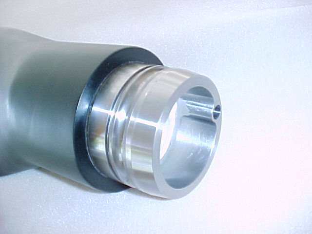
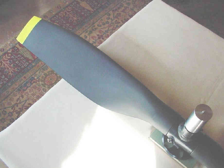
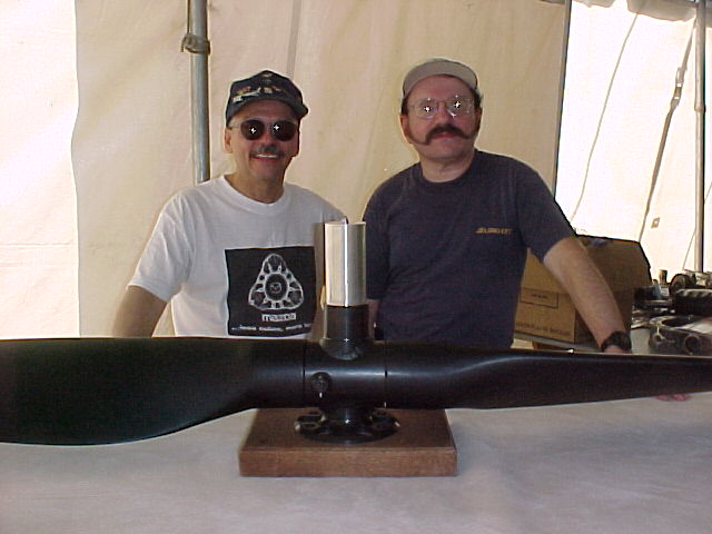
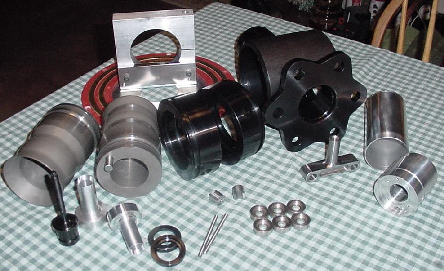
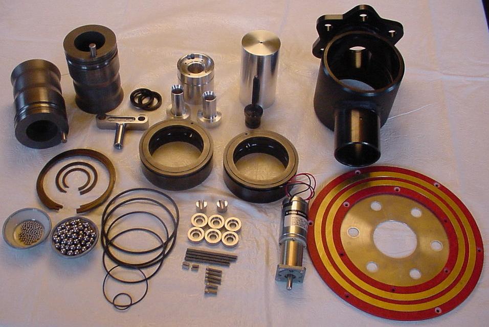
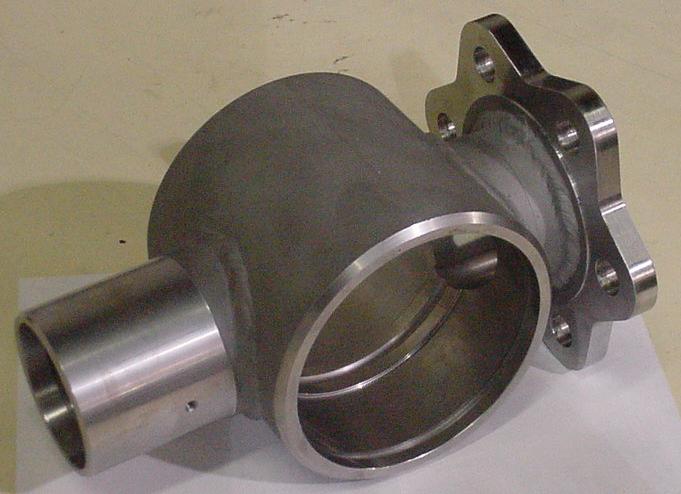
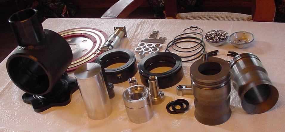
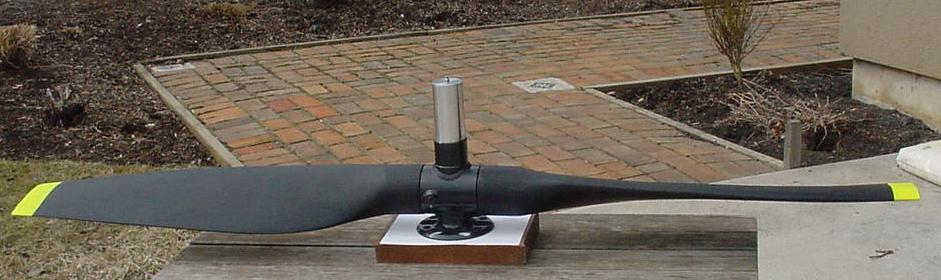
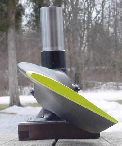
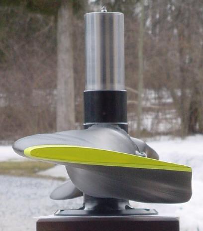
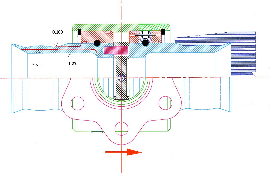
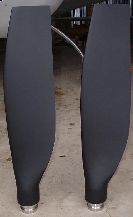
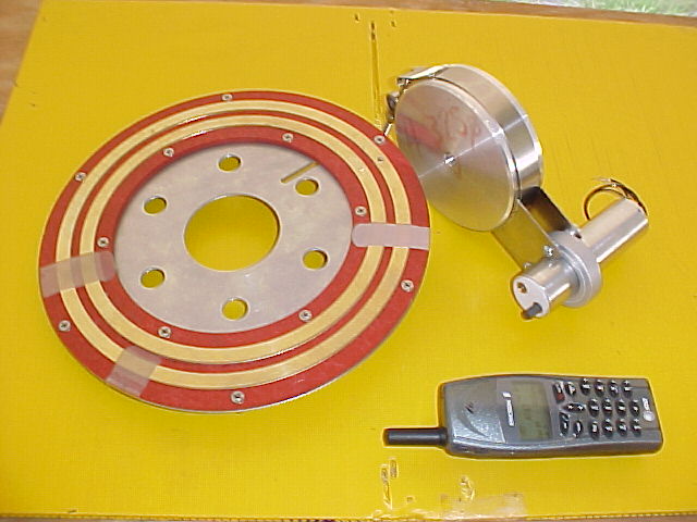
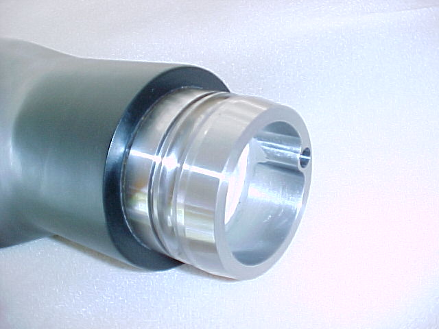
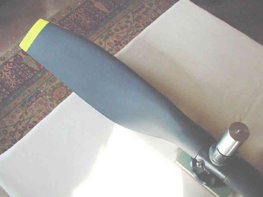
Yes in fact we designed and built one. Here are some pictures.
I did the initial design and others helped out. That was back in
the days we had a viable economy. If you are still interested
I have dwgs and other details.
The fact of the matter the power to weight ratio of a rotary powered
airplane is such
that a lower pitch is not really needed. Set the pitch for optimum
cruise and
let it go with that. Take off and climb are still amazing.
I would consider it for over all aircraft performance competition however.
Paul Lamar
The Rotary Engine free News Letter. Powered by Linux. If you want off
the list PLEASE let me know and I will remove you. ACRE NL web
site.
http://www.rotaryeng.net You Tube
http://tinyurl.com/beqqxas
Copyright 1998-2017 All world wide rights reserved.