My gearbox is on the engine, but if you need the exact shaft diameter
soon, I will be happy to pull the it and measure the shaft.
Other measurements that might be helpful:
distance from front edge of flex plate gear to rear of engine block: 1
5/16” distance from front of Tracy’s adapter plate to engine block (the
total
“open” area between the engine and adapter): 3 1/8”
distance from front of Tracy’s adapter plate to rear face of his
riveted spline adapter: 1 1/4”
the front of the spline adapter appears very close to the rear edge of
the flex plate ring gear.
It appears that the total thickness of a new coupler (for Tracy’s RD)
would need to be the exact distance from the rear face of the bolted
area of the flex plate to the rear of its ring gear, which is the plane
of the front of the riveted part of the spline adapter. This would
maintain the dimensions for the thrust bearings. A coupler that is
more thick than this would move the rest of the RD to the rear, requiring
alteration of the existing spacers (the 3 1/8” distance). A thinner
coupler could be managed with thrust bearing washers.
Scott Gettings
I just happened to have one.
The OD of the part in question is 6.188. The long part that sticks away
from the engine 1.158 long.
The idea is to turn it around and put the long part inside the
coupling. We worked this out years ago :-) 3D's 5 and six show this config.
That steel Ford part raw weighs 3 pounds. There is unnecessary meat on
both sides that I can cut off if you send me yours. That will
give you plenty of room and save a bit of weight. Some of the spline
part can be
cut off as well. 1.25 inches of spline would be plenty.
Jean is down the road from you in Pompano Beach and he might do
it for you. He has a lathe and a mill. He will need one sooner or
later :-)
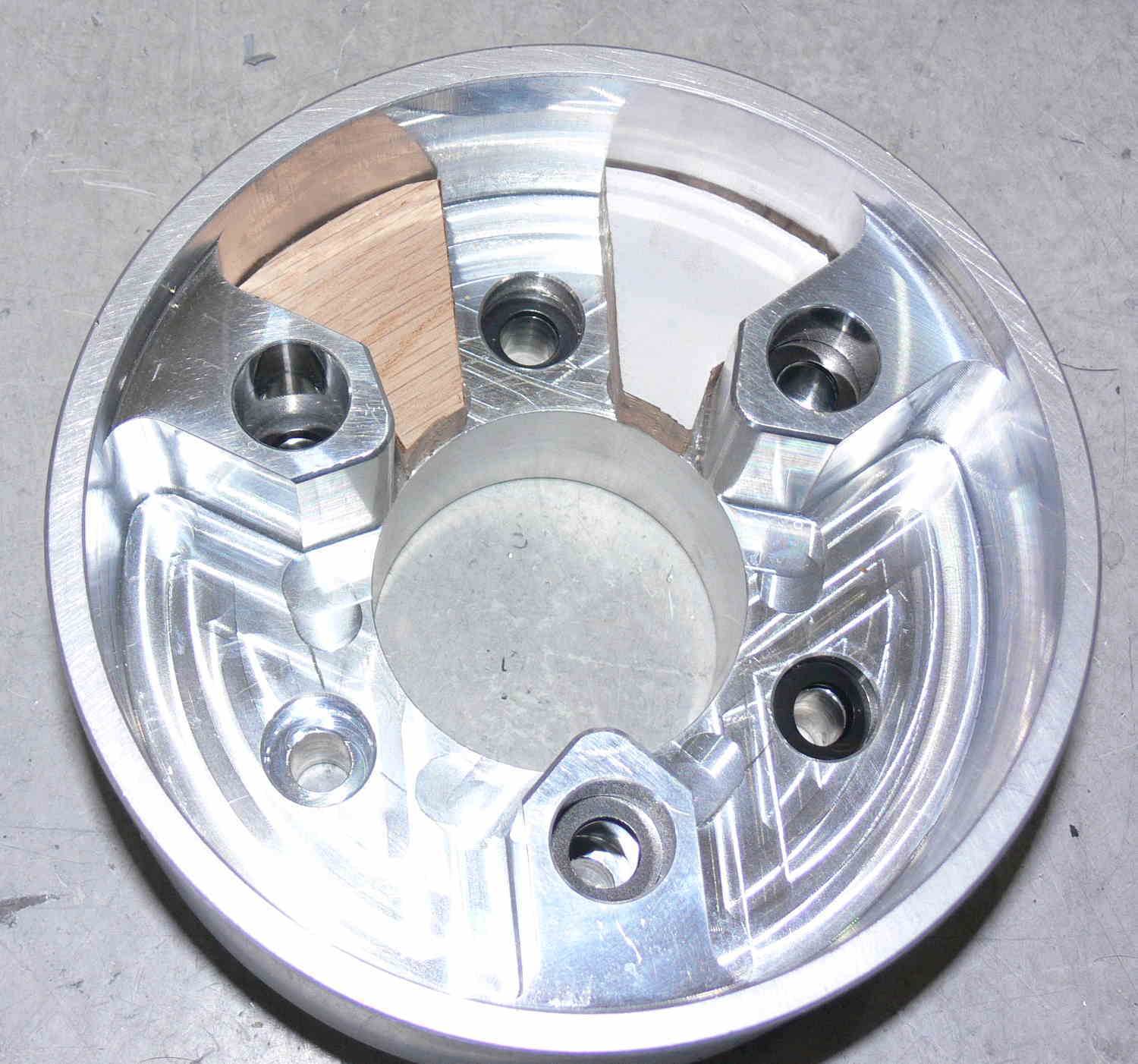
Here are a few pictures.
Paul Lamar
Paul
I revised the drawing and design the stencil template for
waterjet cutter, see attached file for each of them plus
the file as solid parts the back plate to suit the ford plate
as 1.860 Dia where spline shaft attached.
I will get one sample as soon i get the quotation from them.
JEAN PRUDHOMME
Use part of Tracy's torque isolator to adapt this to Tracy's PSRU
input shaft. Drill out the rivets and bolt it to the steel output
front plate.
Paul Lamar
Hi Paul
Before leaving for Canada i did had time to pick up the
watercutter parts for the coupling and it look very nice
with a slight adjstment with filing edges.
I will get it welded on my return.
No doubt about it. This us the best way to build a coupler.
Just cut silicon rubber blocks to fill the gaps.
Paul Lamar
I need to built a thicker back plate for the outside ring like 3/8" or
1/2" thick to be able to reset the bolts head to clear the rubber blocks
, but it will be stronger and easier to tig weld all around the stubs
by the outside the back plate have to be insert 1/4" the rest extend
outside for tig weld jointing the all around without interfering the
back surface with the weld
JEAN PRUDHOMME
Good call Jean. We did that on the TTC. About 3/4 of an inch will do it.
Some supply places will
cut a 6 inch diameter bar to 3/4 of an inch long. The other thing is
just put
some pieces of sheet metal in there to cover the bolt heads.
Paul Lamar
The Rotary Engine free News Letter. Powered by Linux. If you want off
the list PLEASE let me know and I will remove you. ACRE NL web
site.
http://www.rotaryeng.net You Tube
http://tinyurl.com/beqqxas
Copyright 1998-2017 All world wide rights reserved.