Paul
I am the person who designed all the cdi ignitions on our website,
unfortunately i'm not good at reading minds.
The messages received here are incoherent and difficult to understand
also please keep in mind that terminology and acronyms vary from
country to country so its best to keep descriptions basic.
I designed the Pro-14R to be capable of firing two outputs
simultaneously or with any split desired.
If you only have two triggers and want to fire both channels at the
same time you can pair up a leading and trailing trigger.
Our systems are normally triggered by an ecu which provides timing
adjustment however if fixed timing is all you need then the unit can
be triggered with a hall effect sensor.
I am out of the office and only have have access to the documents on
our website. Each instruction manual has both schematics and pin
description.
Wayne M&W
I have one of your rotary ignitions working on a 650 HP two rotor.
It started missing at high RPM so we assumed it was a voltage supply
problem. At 8000 RPM what is the lowest supply voltage that will
work. The spark plug gaps are .025" The ignition is controlled by a
Motec 800.
It has no alternator or voltage regulator so we are installing an 18
volt battery.
The rotary fires once per rev on each rotor.
On a two rotor the firings are 180 degrees out.
Each rotor has two spark plugs. There are 4 spark plugs total.
The spark plugs on one rotor can be fired at the same time or they
can be fired several degrees apart.
Is that clear?
I assume that L1 in your pro14R rotary ignition documentation
instructions stands for the leading spark coil on rotor 1? T1 is the
trailing spark coil? It does not say that in your documentation. It
just says "trigger" what every that means. "Trigger" is a very
general term. If it is a coil what are specs for the pulse?
Is that spelled out in the istallation guide?
Read istallation guide for important wiring details!
Can I get a copy of that guide?
Paul Lamar
Paul
You talk about a Pro-14R however you image you included is for a
Pro-Drag4R, similar function but completely different installation
instructions and power level.
The unit was supplied with an installation guide, if you have lost it
a copy may be downloaded from our website under the support
-Technical Documentation tab. Check the bottom sticker on the box
before downloading as we have both Series 3 and Series 4 versions.
Triggering is explained in the documentation along with trigger edge
and a great deal of important details for achieving a successful
installation. They also list operating voltage and warnings about the
use of 18v battery systems.
As these units are specifically designed for rotary engines L1 means
Leading 1 and T1 means Trailing1 etc.
Did the installation run ok initially with our system installed and
then start misfiring or did the problem start as soon as you
installed the new ignition?
Wayne M&W
I have both the drag and the regular version. The Pro14R and the
pro14R Drag docs.
What is the exact part number for the "installation guide"
I don't see anything named "installation guide" on your web site.
The M&W ignition worked OK at the lower RPM's. He probably ran the
battery down a bit and then he tried a full power run which means up
to 8000 RPM. It is connected to a Motec 800. It was installed by
some one else. He died and did not give us any documentation.
A lead acid battery will lower it's voltage when more current is
needed. As you go up in RPM with a CD system current requirements
increase.
We are now installing an 18 volt battery.
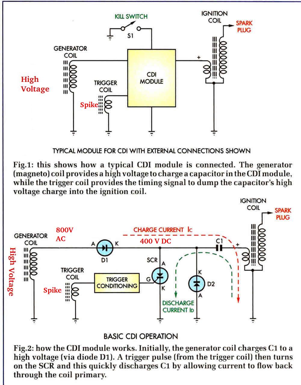
Since I am very familiar with CD ignitions having a patent pending on
one of my designs I know that the high voltage (300 volts) required
to charge the capacitor is very sensitive to primary battery voltage
at less than 12 volts.
Here is a video of my system at 8000 RPM. This is 4 sparks 5 degrees
apart. Patent pending. It will be a revolution in ignition systems
if I get the patent.
This is not to criticize, degrade or compete with your systems. Your
system works fine with the right battery supply voltage for one
spark. I like it as potentially it will work with out a ECU if I can
only figure how to wire it :-) In other words a carburetor-ed
engine.
My next door neighbor manufactures and sells CD systems that work
down to 5 volts but the design engineer set out to do that when he
designed the high voltage capacitor charging supply. His works with
carbs.
It is called Light Speed Engineering ignition. His only works to 2600
RPM for up to six cylinders.
Paul Lamar
What about using a small alternator like used on sub-compact tractors
or zero turn lawn mowers. One of those is probably not much heavier
than the 18 volt system you are thinking of. Of course the alternator
is only one thing to consider for weight as the brakets and belt need
to be included. The advantage with this is you would have a constant
stabile voltage and current supply. In the TTC application you are
not using a lot of high draw loads so you do not need an alternator
of 100Aor 150A output capacity.
Dale Davies
That might work but we don't have an rotating shaft accessible.
Paul Lamar
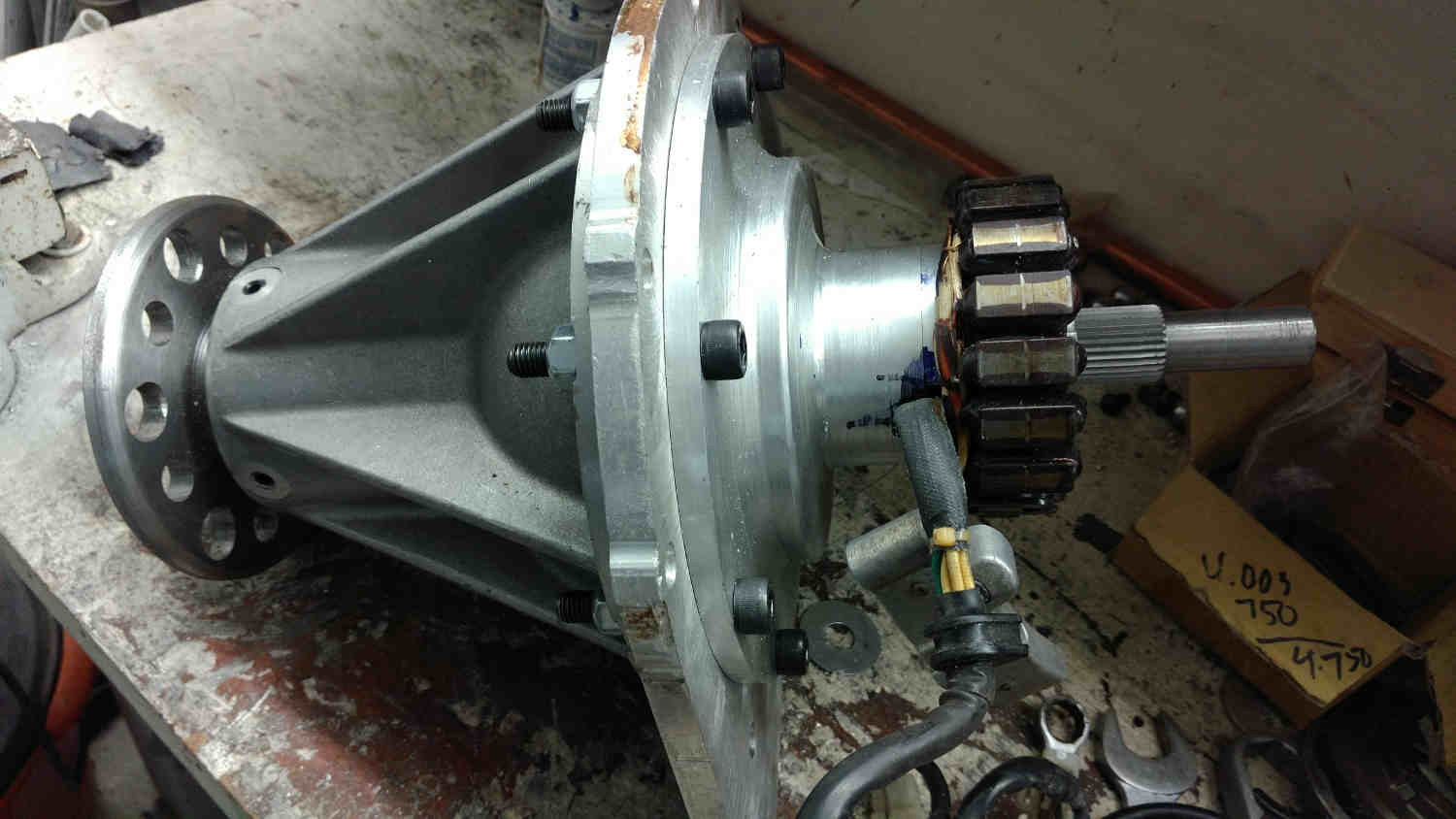
I might suggest putting a couple magnets in the balancer and then
mountain a kohler charging coil in fixed position around it. Good for 20
amps
Regards
Kurt Emerson
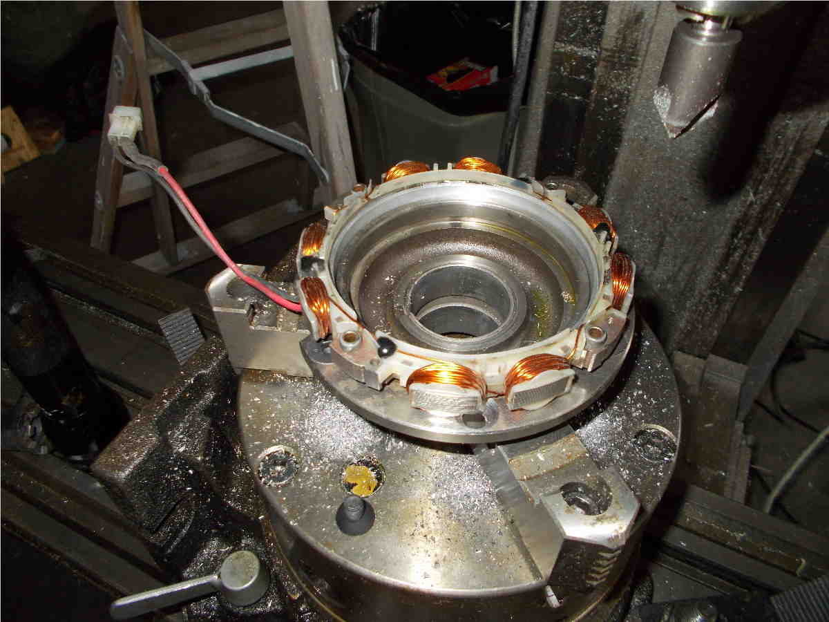
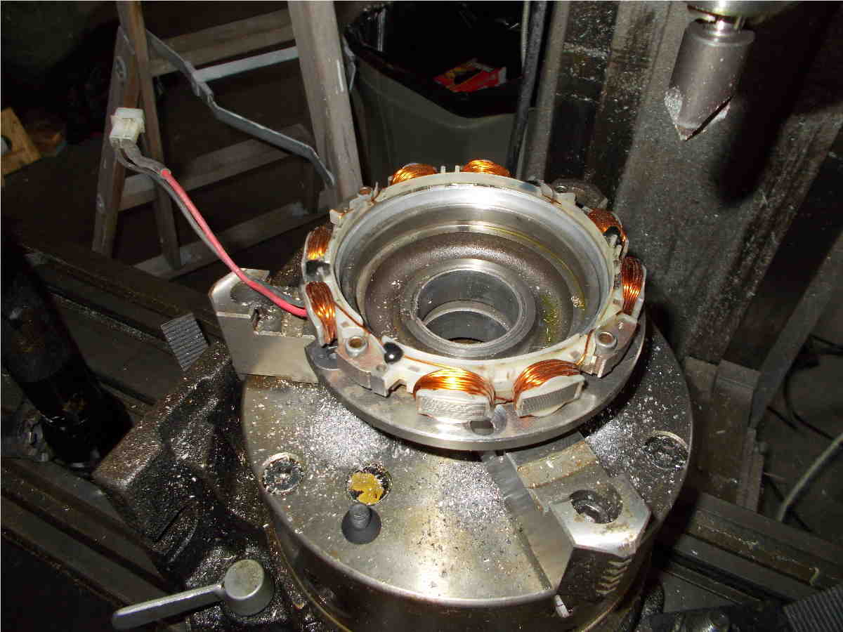
I think you are talking about an outboard motor type of ignition.
We have considered that. Here is Jean Proudhomme and Milo version.
Potentially very reliable and does not depend on an electrical
system. Self contained and simple.
Paul Lamar
The Rotary Engine free News Letter. Powered by Linux. If you want
off the list PLEASE let me know and I will remove you. ACRE NL web
site.
http://www.rotaryeng.net You Tube
http://tinyurl.com/beqqxas
Copyright 1998-2017 All world wide rights reserved.