designed for a two rotor.
It is lower cost by about $150 compared to two Mallorys
Probably $900 lower cost than the M&W.
I could also include two LM1815 circuits that would condition the
pulses out of the stock crank angle sensors for a few dollars more.
If any one wants to build one I can do a circuit board for them.
-------------------------------------------------------------------------------------------
If any body has a 2nd RX7 ignition system the waste spark coil will
work with this CD system. You will need two for a 2 rotor.
This will save you a lot of money. You can buy them cheap on ebay I
am sure.
I found the old LM1815 are no longer available in dips so they must
be surface mounted. Not that hard for this part. It can easily be
done with a small tip on a soldering iron.
---------------------------------------------------- Ops I found
some LM1815 dips on ebay at a great price. Just over a buck apiece.
Steve, get some of these and send some to me. About ten would be
about right.
Here is the schematic with the LM1815 on board. These are wonderful
chips for taking in CAS signals an outputting a simple pulse.
Megasquirt uses them as well. Why they are not making the dip
versions anymore is a mystery to me. Dips are much easier to
experiment with.
Here is the schematic with the LM1815's.
---------------------------------------------------------------------------------------
The other relatively expensive part is the 1 mf high voltage
capacitor that stores the charge. It is 760 volts. I could not find
one with less voltage.
Here it is one Digi Key for $2.83 cents each.
Still working on the transformer.
Paul Lamar
I would be keen for a couple of boards, If you are not making a few
complete units. I already have the coils lying around somewhere.
Richie Barrow
I am not ready to do the PC boards quite yet. Steve Carlisle will
take it over when I get a bit further along.
I usually order 3 PC boards at a time as they are cheaper that way.
------------------------------------------------------
Here is the Express PCB layout for two LM1815 CAS conditioners. 16
pin dip versions.
It is to scale. The resisters are quarter watt as I recall but 1/10
watt would work.
Attached is the pdf on the transformer I will try. I got a free
sample. They about $6 each. If they work they are a real bargain.
This is one of the hardest parts to make.
Paul Lamar
Just about any waste spark coil will work if it does not have a
transistor switch inside or igniter. In general they would have
three connections but not always. Ground, 12 volts and a trigger
connection.
In fact I am not sure if the second gen RX7 Denso will work as I
found a label on on it that said "w/igniter". It only has two
connections. And the primary is about 1 to 2 ohms.
The primary winding on these non transistor coils is about 1 ohm. So
that will draw about 12 amps.
Use an ohmmeter to measure the primary resistance. If it is one or
two OHM it probably is a non transistor coil. The RX7 second gen
waste spark coil was about 1.5 ohms so I assumed the 2nd gen igniter
fired it.
If you connect a heavy duty push button switch from the negative side
of the coil to ground and a 12 volt battery connected to the plus
side it will fire a simple, old non transistor coil with a spark
plug connected when you tap the switch.
Any coil used with a distributer with points is a non transistor
coil.
Paul Lamar
I will be interested in these boards, as I have been unsuccessful in
obtaining local assistance with Tracyâs ECU and donât want to be
in a totally unsupported environment in the future. All of my local
IT guys say the environment is too old and it would be a very long
project to get it all updated and running.
Hopefully the outcome of all of this great work will result in a CDI
and EFI environment that those of us with less expertise in this area
can install and operate. The CDI units in the $150 range seem
reasonable, but the $1500 solutions are out of reach. Paul I scanned
my old emails and did not find the one where you listed example
Maximize code for the EFI. Can you please re-post?
BTW, I have completed the header/muffler for my installation. A
few pix are attached, including one showing the internals. The
internal holes are equivalent in area to the 3â tailpipe.
It ended up being a little heavier than anticipated (13 lb, 5 of
which is the Racing Beat header flange), as well as a little bigger.
This is close to the weight of the stock header alone. Width: my
cowl will need to handle 14â from center on this side, although I
could have part of the cylinder outside of a more narrow cowling,
which might cool better. 14â is about as wide as a horizontal
piston engine. I can shed possibly another pound or so and narrow
the slip joints 3/4â if needed. Note that the 1/ 1/2â tube
running through the cylinder is for cooling air flow and does not
connect with the exhaust. I looked at installing it on my RX-8 as a
test, but that it is not practical. If anyone has a running renesis
engine and would like to borrow it for testing, please let me know.
Scott Gettings
Once you take the ignition problem out of the computer the EFI part
becomes much simpler. A very simple system will keep the engine
running while you can tune it with a manual mixture control. A simple
bench set up consisting of mass air flow sensor, a Maximite and a
transistor controlling a fuel injector goes a long way towards
developing a simple system that will work.
In fact you don't need a real mass airflow sensor as a small pot
connected to five volts can simulate a mass air flow sensor variable
voltage.
Boils down to reading the mass air flow sensor and adjusting the
pulse width on the injector depending on how much air is going into
the engine.
It can do this ten times a second or faster.
It is easier than a car EFI system as you have a well defined prop
load that is a simple function of RPM. No rapid acceleration is
needed.
Paul Lamar
One of the recent aps for smart phones are oscilloscope aps. This
makes it possible to actually see the pulses applied to the
injectors and measure their width with out spending $300 or more for
an oscilloscope.
They are also available for computers.
This is a major cost reduction when developing EFI software.
----------------------------------------------------------------------
You must be very careful when using these oscilloscope for
computers or cell phones that you don't put in too much voltage.
Usually they use the microphone jack which is designed for very low
voltage.
There is a company that sells some hard ware that uses the screen of
your cell phone by connecting to it with blue tooth. That is much
safer but it cost about $160. Works with cell phones and computers
that have blue tooth.
https://ar-oscilloscope.com/products/
They also have low cost probes which are almost essential.
These will trouble shoot your CAS no matter how your using it. Stock
or other wise.
Here is a larger picture of the LM1815 PC board.
The front rotor CAS can also be used to trigger the EFI in addition
to the ignition.
Paul Lamar
I actually have an oscilloscope sitting on a shelf. Now if I just
knew how to use it.... :-)
Scott Gettings
Take a picture of the front panel and I will explain the controls.
What brand is it?
Paul Lamar
Ramsey. Here are the pictures. It looks like it is virtually new in
the box. It has a complete instruction manual which should cover
it's basic functions. I would most benefit from knowing how it would
specifically be used in the current systems under development
Thx
Scott Gettings
designed for a two rotor.
It is lower cost by about $150 compared to two Mallorys
Probably $900 lower cost than the M&W.
I could also include two LM1815 circuits that would condition the
pulses out of the stock crank angle sensors for a few dollars more.
If any one wants to build one I can do a circuit board for them.
-------------------------------------------------------------------------------------------
If any body has a 2nd RX7 ignition system the waste spark coil will
work with this CD system. You will need two for a 2 rotor.
This will save you a lot of money. You can buy them cheap on ebay I
am sure.
I found the old LM1815 are no longer available in dips so they must
be surface mounted. Not that hard for this part. It can easily be
done with a small tip on a soldering iron.
---------------------------------------------------- Ops I found
some LM1815 dips on ebay at a great price. Just over a buck apiece.
Steve, get some of these and send some to me. About ten would be
about right.
Here is the schematic with the LM1815 on board. These are wonderful
chips for taking in CAS signals an outputting a simple pulse.
Megasquirt uses them as well. Why they are not making the dip
versions anymore is a mystery to me. Dips are much easier to
experiment with.
Here is the schematic with the LM1815's.
---------------------------------------------------------------------------------------
The other relatively expensive part is the 1 mf high voltage
capacitor that stores the charge. It is 760 volts. I could not find
one with less voltage.
Here it is one Digi Key for $2.83 cents each.
Still working on the transformer.
Paul Lamar
I would be keen for a couple of boards, If you are not making a few
complete units. I already have the coils lying around somewhere.
Richie Barrow
I am not ready to do the PC boards quite yet. Steve Carlisle will
take it over when I get a bit further along.
I usually order 3 PC boards at a time as they are cheaper that way.
------------------------------------------------------
Here is the Express PCB layout for two LM1815 CAS conditioners. 16
pin dip versions.
It is to scale. The resisters are quarter watt as I recall but 1/10
watt would work.
Attached is the pdf on the transformer I will try. I got a free
sample. They about $6 each. If they work they are a real bargain.
This is one of the hardest parts to make.
Paul Lamar
Just about any waste spark coil will work if it does not have a
transistor switch inside or igniter. In general they would have
three connections but not always. Ground, 12 volts and a trigger
connection.
In fact I am not sure if the second gen RX7 Denso will work as I
found a label on on it that said "w/igniter". It only has two
connections. And the primary is about 1 to 2 ohms.
The primary winding on these non transistor coils is about 1 ohm. So
that will draw about 12 amps.
Use an ohmmeter to measure the primary resistance. If it is one or
two OHM it probably is a non transistor coil. The RX7 second gen
waste spark coil was about 1.5 ohms so I assumed the 2nd gen igniter
fired it.
If you connect a heavy duty push button switch from the negative side
of the coil to ground and a 12 volt battery connected to the plus
side it will fire a simple, old non transistor coil with a spark
plug connected when you tap the switch.
Any coil used with a distributer with points is a non transistor
coil.
Paul Lamar
I will be interested in these boards, as I have been unsuccessful in
obtaining local assistance with Tracyâs ECU and donât want to be
in a totally unsupported environment in the future. All of my local
IT guys say the environment is too old and it would be a very long
project to get it all updated and running.
Hopefully the outcome of all of this great work will result in a CDI
and EFI environment that those of us with less expertise in this area
can install and operate. The CDI units in the $150 range seem
reasonable, but the $1500 solutions are out of reach. Paul I scanned
my old emails and did not find the one where you listed example
Maximize code for the EFI. Can you please re-post?
BTW, I have completed the header/muffler for my installation. A
few pix are attached, including one showing the internals. The
internal holes are equivalent in area to the 3â tailpipe.
It ended up being a little heavier than anticipated (13 lb, 5 of
which is the Racing Beat header flange), as well as a little bigger.
This is close to the weight of the stock header alone. Width: my
cowl will need to handle 14â from center on this side, although I
could have part of the cylinder outside of a more narrow cowling,
which might cool better. 14â is about as wide as a horizontal
piston engine. I can shed possibly another pound or so and narrow
the slip joints 3/4â if needed. Note that the 1/ 1/2â tube
running through the cylinder is for cooling air flow and does not
connect with the exhaust. I looked at installing it on my RX-8 as a
test, but that it is not practical. If anyone has a running renesis
engine and would like to borrow it for testing, please let me know.
Scott Gettings
Once you take the ignition problem out of the computer the EFI part
becomes much simpler. A very simple system will keep the engine
running while you can tune it with a manual mixture control. A simple
bench set up consisting of mass air flow sensor, a Maximite and a
transistor controlling a fuel injector goes a long way towards
developing a simple system that will work.
In fact you don't need a real mass airflow sensor as a small pot
connected to five volts can simulate a mass air flow sensor variable
voltage.
Boils down to reading the mass air flow sensor and adjusting the
pulse width on the injector depending on how much air is going into
the engine.
It can do this ten times a second or faster.
It is easier than a car EFI system as you have a well defined prop
load that is a simple function of RPM. No rapid acceleration is
needed.
Paul Lamar
One of the recent aps for smart phones are oscilloscope aps. This
makes it possible to actually see the pulses applied to the
injectors and measure their width with out spending $300 or more for
an oscilloscope.
They are also available for computers.
This is a major cost reduction when developing EFI software.
----------------------------------------------------------------------
You must be very careful when using these oscilloscope for
computers or cell phones that you don't put in too much voltage.
Usually they use the microphone jack which is designed for very low
voltage.
There is a company that sells some hard ware that uses the screen of
your cell phone by connecting to it with blue tooth. That is much
safer but it cost about $160. Works with cell phones and computers
that have blue tooth.
https://ar-oscilloscope.com/products/
They also have low cost probes which are almost essential.
These will trouble shoot your CAS no matter how your using it. Stock
or other wise.
Here is a larger picture of the LM1815 PC board.
The front rotor CAS can also be used to trigger the EFI in addition
to the ignition.
Paul Lamar
I actually have an oscilloscope sitting on a shelf. Now if I just
knew how to use it.... :-)
Scott Gettings
Take a picture of the front panel and I will explain the controls.
What brand is it?
Paul Lamar
Ramsey. Here are the pictures. It looks like it is virtually new in
the box. It has a complete instruction manual which should cover
it's basic functions. I would most benefit from knowing how it would
specifically be used in the current systems under development
Thx
Scott Gettings
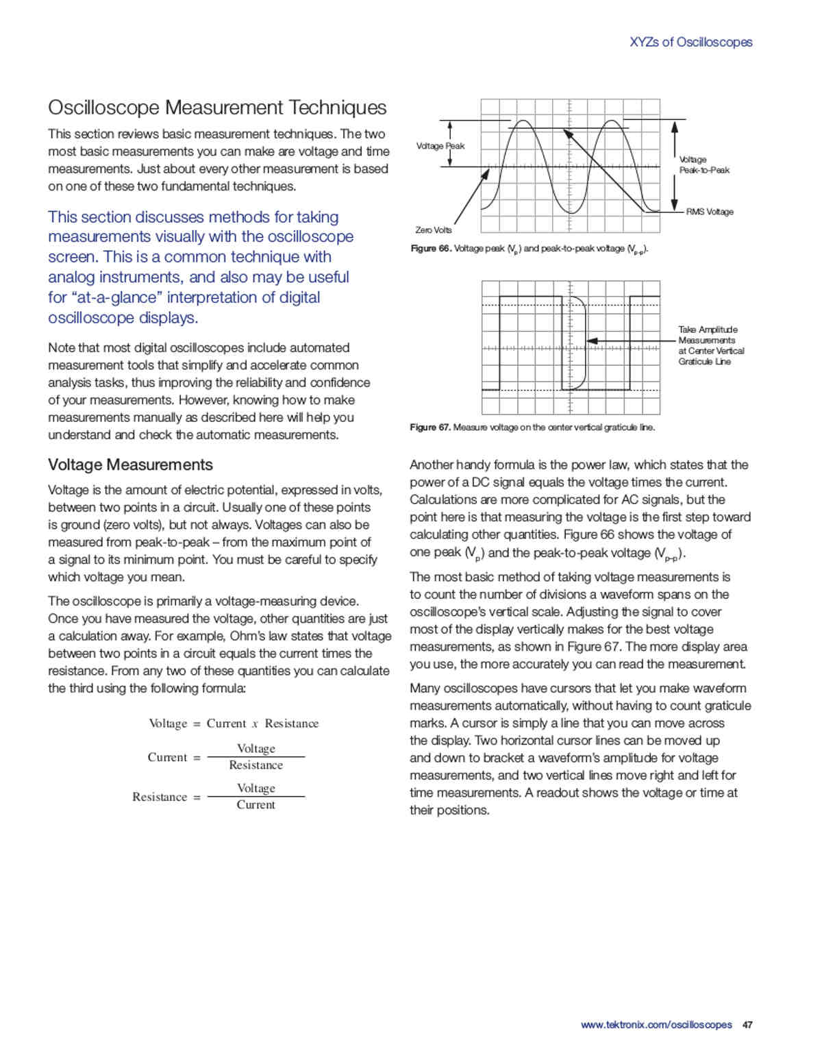
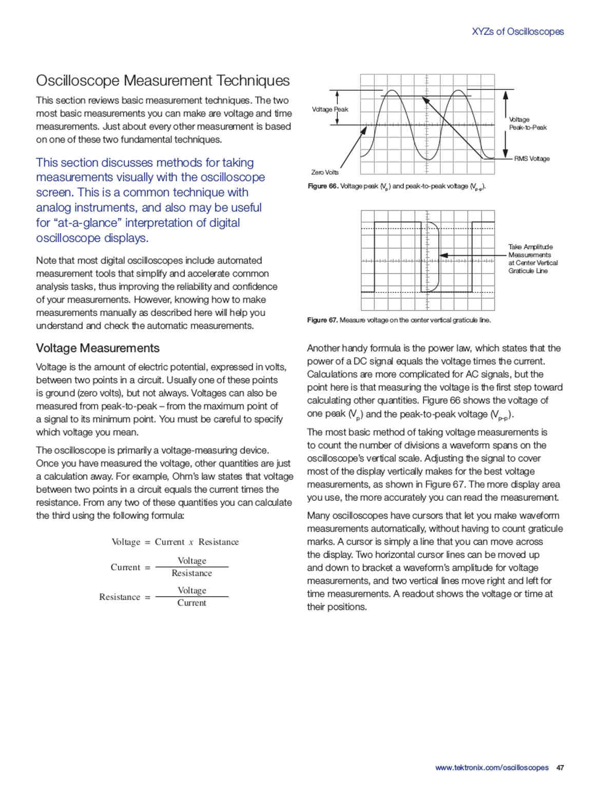
The oscilloscope is basically a graph-displaying device - it draws a
graph of an electrical signal. In most applications the graph shows
how signals change over time: the vertical (Y) axis represents
voltage and the horizontal (X) axis represents time. ... You can
determine the time and voltage values of a signal.
It draws by sweeping a tiny beam of electrons from left to right at
high speed. The screen is divide into what are called "divisions".
Controlled by the upper red knob. One division can be set to say....
one millisecond or one ms. It can be as short as one microsecond (one
usec) with a very high speed scope.
The screen is also divided south to north by voltage divisions. The
number of volts per division is set by the lower red knobs. Since
this is a dual trace scope there are two lower red knobs. Each
division can be set to say.... one volt.
More later. Got to go out.
------------------------------------------
A very quick way to understand an O-scope is set the top knob on one
second per division and the bottom knob on one volt per division.
Then get any size 1.5 volts battery and ground the negative side to
the probe. Tap the positive side of the prob tip to the top or
positive side of the battery and watch the o-scope screen.
You will see see some rectangular waves more or less.
Paul Lamar
Hey Paul,
I'm not sure that this file will transfer. Might be too big.
Mark LaPierre
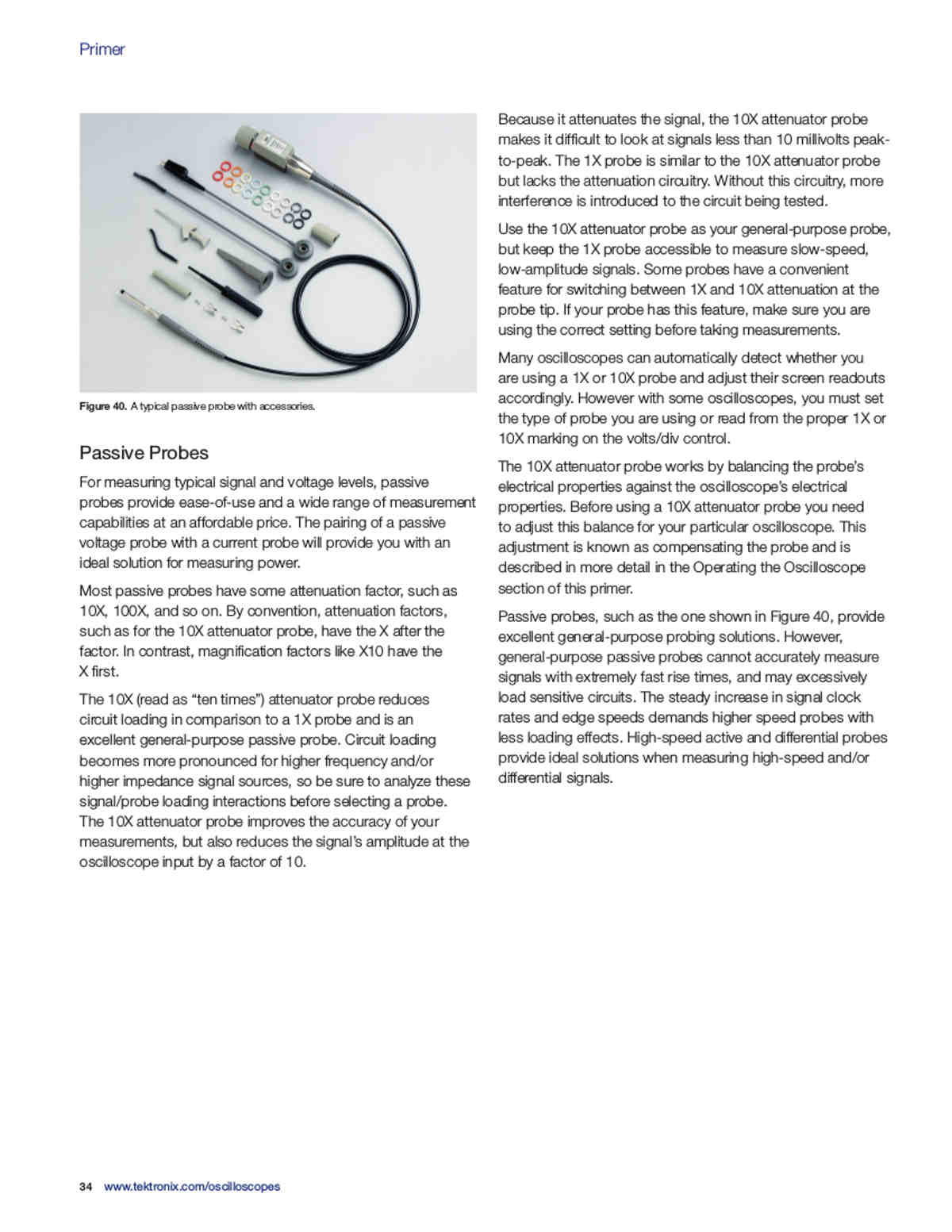
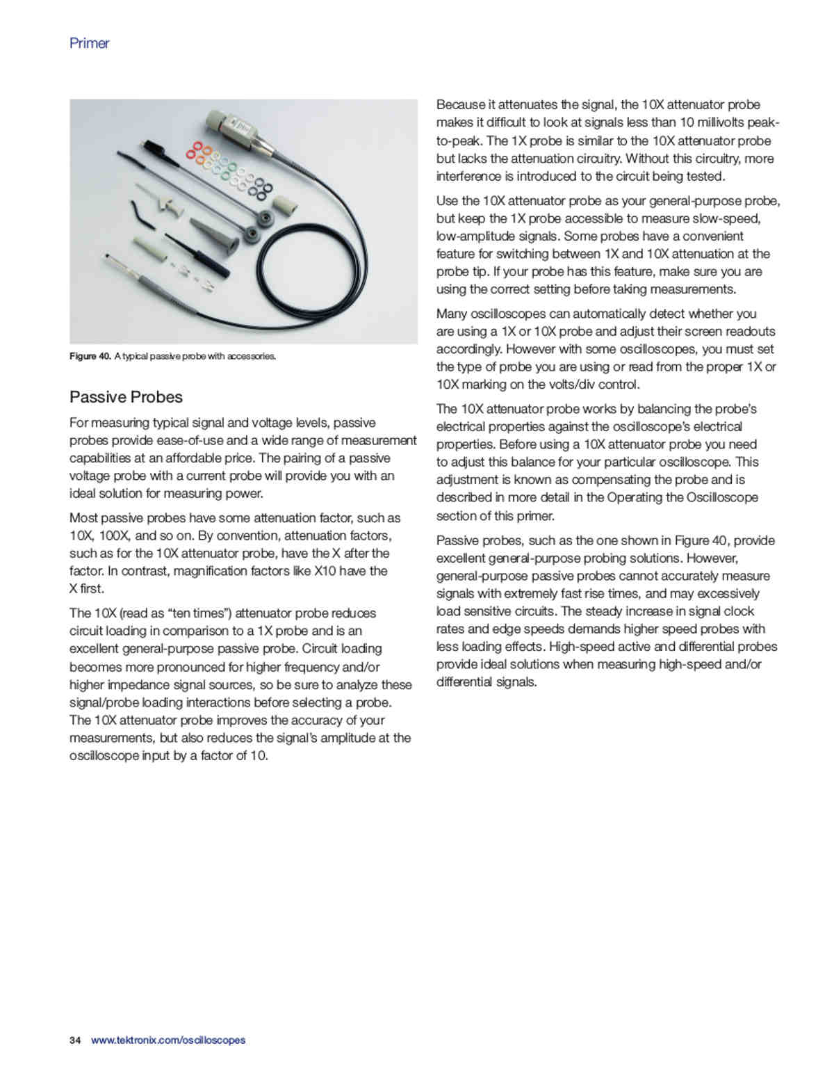
Yes it was. Here is page 47 voltage measurement and page 34 probes.
Paul Lamar
The Rotary Engine free News Letter. Powered by Linux. If you want off
the list PLEASE let me know and I will remove you. ACRE NL web
site.
http://www.rotaryeng.net You Tube
http://tinyurl.com/beqqxas
Copyright 1998-2017 All world wide rights reserved.