Paul,
I ordered 2 RX 8 crank angle sensors and am fabricating a bracket to
mount the sensors.
Room is tight due to modified water pump and heat shield for the
augmenter.
Could you explain how the Mighty Mite will use the pulse generated by
the sensors and the one tit trigger wheel?
The first pulse would be firing ignition by the CDI and the MM would
know 20 degrees BTDC,
Does it look for the second pulse to get a time frame for one rev of
the Eshaft?
What happens next?
What would the code look like?
Thanks
Joe Berki
There is no code for the CD ignition. The maximite does not need to
be involved.
The front rotor (car) fires from the first CAS at 22 degree BTDC.
Then the second CAS 180 degrees later fires the rear rotor. That is
all there is to it.
That reminds me I need to check and see if I got the sample
transformer for the CD system.
Now the CAS can also be connected to the Maximite to fire the
injectors after it checks the mass airflow sensor and figures out the
correct pulse width.
Paul Lamar
This part is what I was trying to understand I know the CDI is
independent.
I wanted to know how the Maximite fires the injectors.
Joe Berki
The Maximite has 20 I/O pins numbered 1 to 20,
All of these pins can be configured as digital out puts or
something else.
The pin will put out 5 volts.
You choose the pin you want to control the injector.
Then it must first be configured.
The instruction is "SETPIN pin, cfg"
"pin" is simple the pin number you choose.
Let say you choose pin number 2
The instruction is then written SETPIN 2
cfg stands for configure.
Here is a list of possible configurations for most pins.
0 Not configured or inactive
1 Analog input (pins 1 to 10)
2 Digital input (all pins and 5V tolerant on pins 11 to 20)
3 Frequency input
4 Period input
(pins 11 to 14)
(pins 11 to 14)
5 Counting input
(pins 11 to 14)
6 Interrupt on low to high input change (pins 1 to 20, D0 to D8)
for target
7 Interrupt on high to low input change (pins 1 to 20, D0 to D8)
for target
8 Digital output (all pins)
9 Open collector digital output to 5V (pins 11 to 20, D0 to D13) In
this mode the
function PIN() will also return the output value.
We want to make it and out put pin so we choose # 8
The instruction is then written like this SETPIN 2, 8
That is all we have to do to configure pin #2 as an output pin.
>From now on it is an output pin.
Now when we tell pin to go high the injector will be fired.
PIN(2) = high turns the injector pulse on 5V
We wait. The wait time is a function of the mass airflow sensor.
PIN(2) = zero turn the injector pin off.
That's it.
You have to get a Maximite and play with it.
You can use a volt meter to check your program.
Programming is mostly trying things and see if it does what
you want it to do.
Paul Lamar
Generally for EFI the injectors are all wired to 12V on the power pin
with a parrallel supply.
Then each injector is grounded through the computer to turn it on. This
is electrically safer
due to less chance of voltage spikes.
Dale Davies
Yes. you need a 12 Volt switching transistor to turn the injector on and
off.
The 5 volt pulse out of the Maximite triggers the switching transistor.
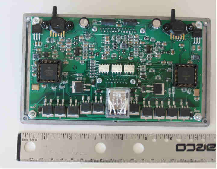
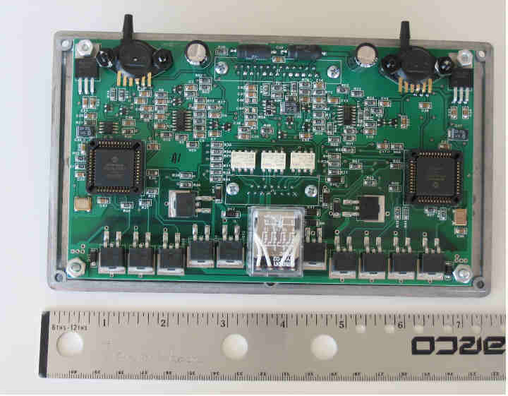
The transistors on the bottom of Tracy board are the injector transistors.
Paul Lamar
The Rotary Engine free News Letter. Powered by Linux. If you want
off the list PLEASE let me know and I will remove you. ACRE NL web
site.
http://www.rotaryeng.net You Tube
http://tinyurl.com/beqqxas
Copyright 1998-2017 All world wide rights reserved.