Paul,
I ordered 2 RX 8 crank angle sensors and am fabricating a bracket to
mount the sensors.
Room is tight due to modified water pump and heat shield for the
augmenter.
Could you explain how the Mighty Mite will use the pulse generated
by the sensors and the one tit trigger wheel?
The first pulse would be firing ignition by the CDI and the MM would
know 20 degrees BTDC,
Does it look for the second pulse to get a time frame for one rev of
the Eshaft?
What happens next?
What would the code look like?
Thanks
Joe Berki
There is no code for the CD ignition. The maximite does not need to
be involved.
The front rotor (car) fires from the first CAS at 22 degree BTDC.
Then the second CAS 180 degrees later fires the rear rotor. That is
all there is to it.
That reminds me I need to check and see if I got the sample
transformer for the CD system.
Now the CAS can also be connected to the Maximite to fire the
injectors after it checks the mass airflow sensor and figures out
the correct pulse width.
Paul Lamar
This part is what I was trying to understand I know the CDI is
independent.
I wanted to know how the Maximite fires the injectors.
Joe Berki
The Maximite has 20 I/O pins numbered 1 to 20, All of these pins can
be configured as digital out puts or something else. The pin will put
out 5 volts.
You choose the pin you want to control the injector.
Then it must first be configured. The instruction is "SETPIN pin,
cfg" "pin" is simple the pin number you choose. Let say you choose
pin number 2
The instruction is then written SETPIN 2
cfg stands for configure. Here is a list of possible configurations
for most pins.
0 Not configured or inactive 1 Analog input (pins 1 to 10) 2 Digital
input (all pins and 5V tolerant on pins 11 to 20) 3 Frequency input 4
Period input (pins 11 to 14) (pins 11 to 14) 5 Counting input (pins
11 to 14) 6 Interrupt on low to high input change (pins 1 to 20, D0
to D8) for target 7 Interrupt on high to low input change (pins 1 to
20, D0 to D8) for target 8 Digital output (all pins) 9 Open
collector digital output to 5V (pins 11 to 20, D0 to D13) In this
mode the function PIN() will also return the output value.
We want to make it and out put pin so we choose # 8
The instruction is then written like this SETPIN 2, 8
That is all we have to do to configure pin #2 as an output pin.
From now on it is an output pin.
Now when we tell pin to go high the injector will be fired.
PIN(2) = high turns the injector pulse on 5V We wait. The wait
time is a function of the mass airflow sensor. PIN(2) = zero turn
the injector pin off.
That's it.
You have to get a Maximite and play with it. You can use a volt meter
to check your program. Programming is mostly trying things and see if
it does what you want it to do.
Paul Lamar
Paul,
The hardware is the easy part I wanted to know where to start with
the software after the pins are configured. The 2 RX 8 sensors wil
deliver a pulse when the CDI fires for both rotors. The Maximite
looks at this and will fire the injector and keep it on based on the
MAF sensor voltage. What computations need to take place to determine
when to fire the injector based on ignition data? The pulses and the
time between the first pulse and the second pulse will give unit time
per revolution. The injection would be based on an event that already
occurred. Does the rear rotor pulse drive the front rotor Maximize
for injection?
Joe Berki
Do you have a Maximite yet?
I had a brilliant idea yesterday to drastically simplify the code.
You use a FOR NEXT loop to time the injection,
The code would then look like this.
PIN(2) = high turns the injector pulse on 5V when the CAS occurs.
FOR y = 1 to xxxx NEXT PIN(2) = zero turn the injector pin off.
xxxx becomes proportional to the mass air flow reading.
That's it !!!!!! Your done !!!!!!!
One Maximite per rotor.
If I could only get a patent on this ROFL
Paul Lamar
Joe, the fuel system is independent from ignition. It starts up as
soon as the mass airflow senses the cranking sequence.
Steve Carlisle
Google FOR NEXT LOOPs.
There is at least a half dozen explanations. I was amazed.
---------------------------------------------------------------
One of the things you must do when converting the MAF sensor data to
the required width of the pulse is know how much fuel will be
injected for a given pulse width.
I found a great site for calculation the size of the injector you
will need.
http://www.witchhunter.com/injectorcalc1.php
<
http://www.witchhunter.com/injectorcalc1.php This screen capture
jpg shows that you will need 4 injectors
420 cc/min to generate 250 HP full rich at a BSFC of .65 pounds of
fuel per HP per hour. The RX8 yellow injectors alone won't handle
it.
You will need 41 pounds per hour from each injector. 41 pounds is
6.56 gallons per injector.
Now we need to have a chart for the injector chosen that shows the
flow rate per millisecond of opening time. I am working on it.
Paul Lamar
Paul, and more info from th guy that made the injector chart,
http://users.erols.com/srweiss
Steve Carlisle
Paul,
I am still missing something.
The CDI will work off of the 2 RX-8 sensors mounted on the from cover
using the one tit trigger wheel.
Does the 2 Maxi Mite setup then use the 2nd gen CAS to drive it?
I thought for some reason that that CAS could be eliminated.
Thanks
Joe Berki
You mean the thing that looks like a distributor? Yes you can get rid of
that.
The 2 RX8 CAS's will trigger the Maximites as well. You can get a clean
CAS pulse from the LM1815's on the dual CD board.
BTW You can use the Maximite to calibrate an injector.
You can set a pulse width using the Maximite and fire the injector
once and measure the amount of fuel that comes out.
You can trigger this with a push button in place of the CAS.
Then you can set another different pulse width and measure it again.
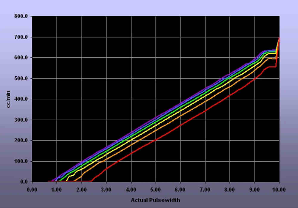
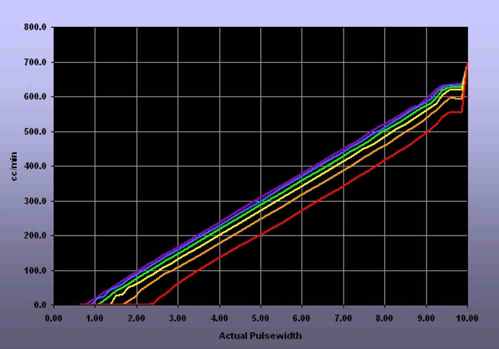
Pretty soon you will have a chart that looks like this.
The max rotary injector pulse width is about 7 ms. At 8000 RPM it takes
only 8 ms to make one rev. So if you are firing the injector every
rev you are limited to about 7 ms. This is known as "timed injection".
You need an injector that will squired enough fuel in 7 ms.
What we did on the TTC is upped the fuel pressure so it would
squirt more in a given pulse width.
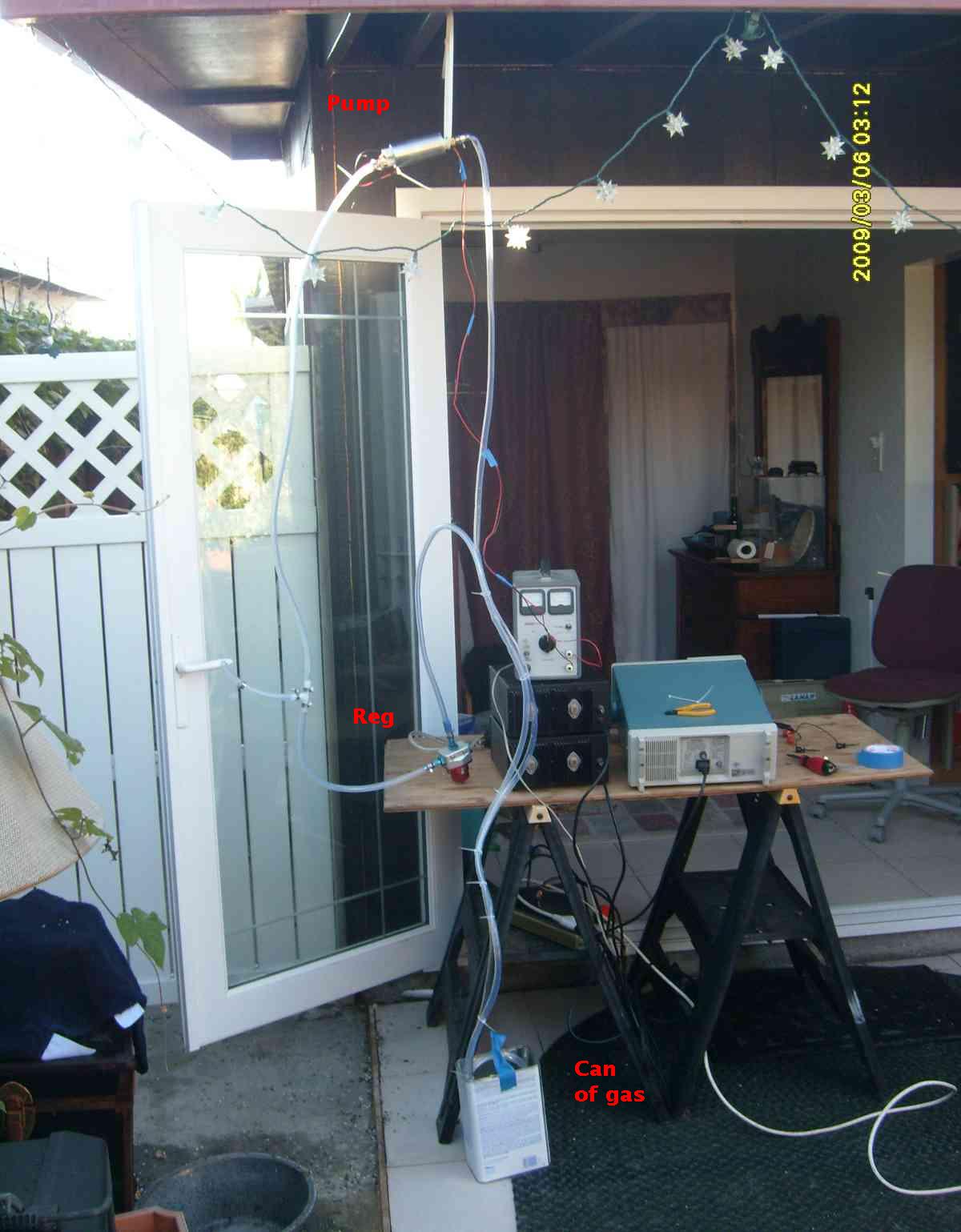
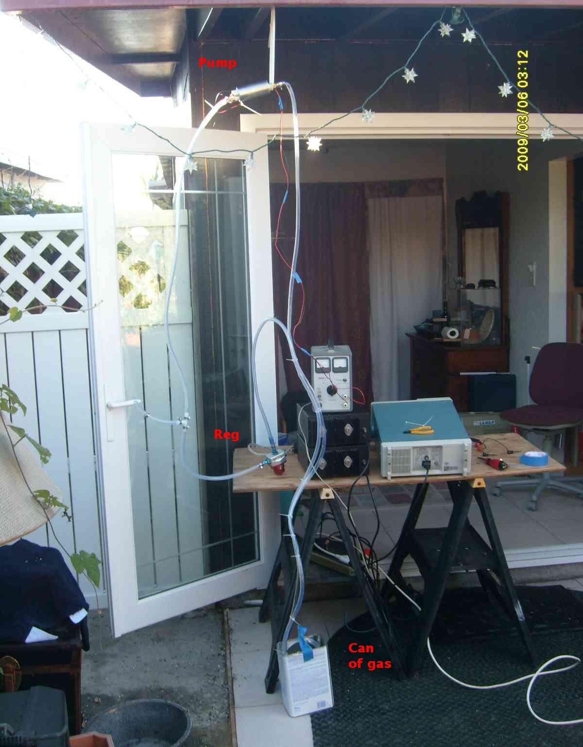
The video was done differently. It is just to show the test set up.
I did it in my back yard so I would not smell up my office :-)
The Maximite is very very handy device for all sorts of things.
Paul Lamar
The Rotary Engine free News Letter. Powered by Linux. If you want
off the list PLEASE let me know and I will remove you. ACRE NL web
site.
http://www.rotaryeng.net You Tube
http://tinyurl.com/beqqxas
Copyright 1998-2017 All world wide rights reserved.