Paul,
Can the RX-8 sensors work in a
reverse logic scenario?
Use a solid metal trigger wheel
with a hole instead of a tit,
The voltage would be high until
the sensor saw the hole.
Use an inverter chip before the
CDI or MaxiMite permitting
triggering on the negative
pulse.
Probably adds more issues or
trading one set of problems for
another.
Joe Berki
That is not how they work. They work on
a change in magnetic
properties. They might work with a
hole. Make a test plate
and chuck in a drill motor. If you have
a scope you will see what
the pulse, if any, looks like. Take a
picture of the scoop face.
The best thing is get a water jet
company to make the plate
as you need the elongated mounting
holes for timing adjustments.
Your email editor is inserting blank
lines between sentences
for some strange reason :-)
Paul Lamar
Paul,
This is what I use to time my combustion pressure tester.
I used an optical sensor at first but it was very intermittent.
When we switched to the Hall Effect sensor HET it became very reliable.
There are slots cut into the standard 3rd gen timing wheel.
(The shinny surface was used for the optical sensor).
Barry Bordes
Yes. They are easier to mount. Much much smaller in some
cases. This one looks
about the same or larger than some wheel magnetic sensors.
Paul Lamar
This picture shows a magnetic pickup sensor, similar to ones used
on the flywheEl of industrial Diesell. They generate a sine wave, to
appropriate decoderived, usually inside the tach. Some say they are
hall effect. I am doubtfully, not looking at all similar to the hall
effect sensors I have seen. A metal disc goes between 2 sides of the
hall effect. Most always on this topic, I need to be educated.
Stee Carlisle
They do make some of them that look like that.
Paul Lamar
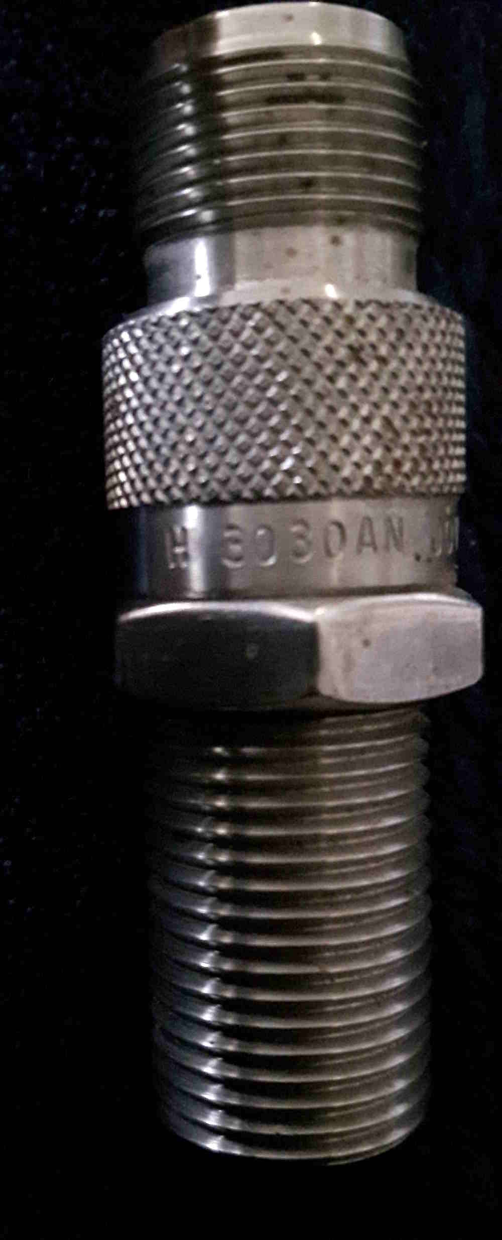
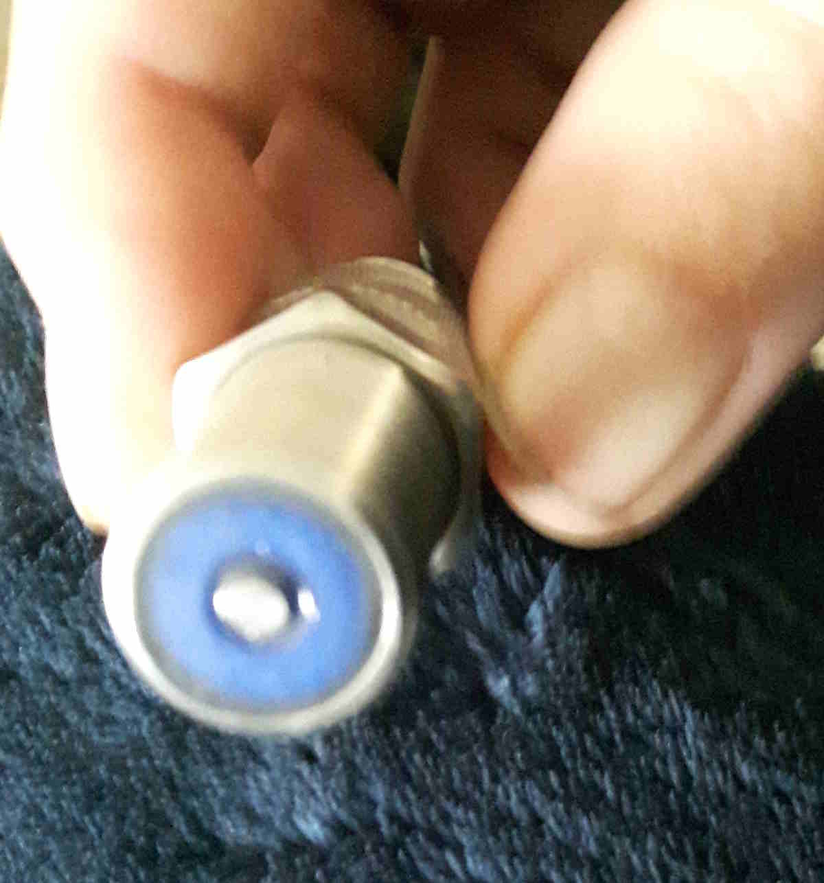
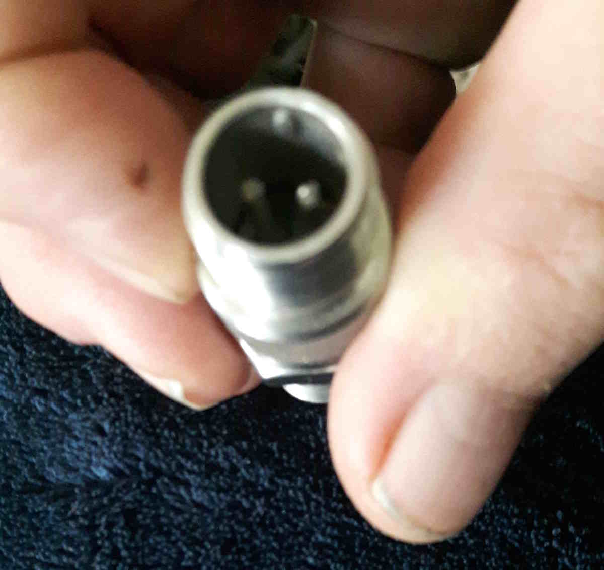
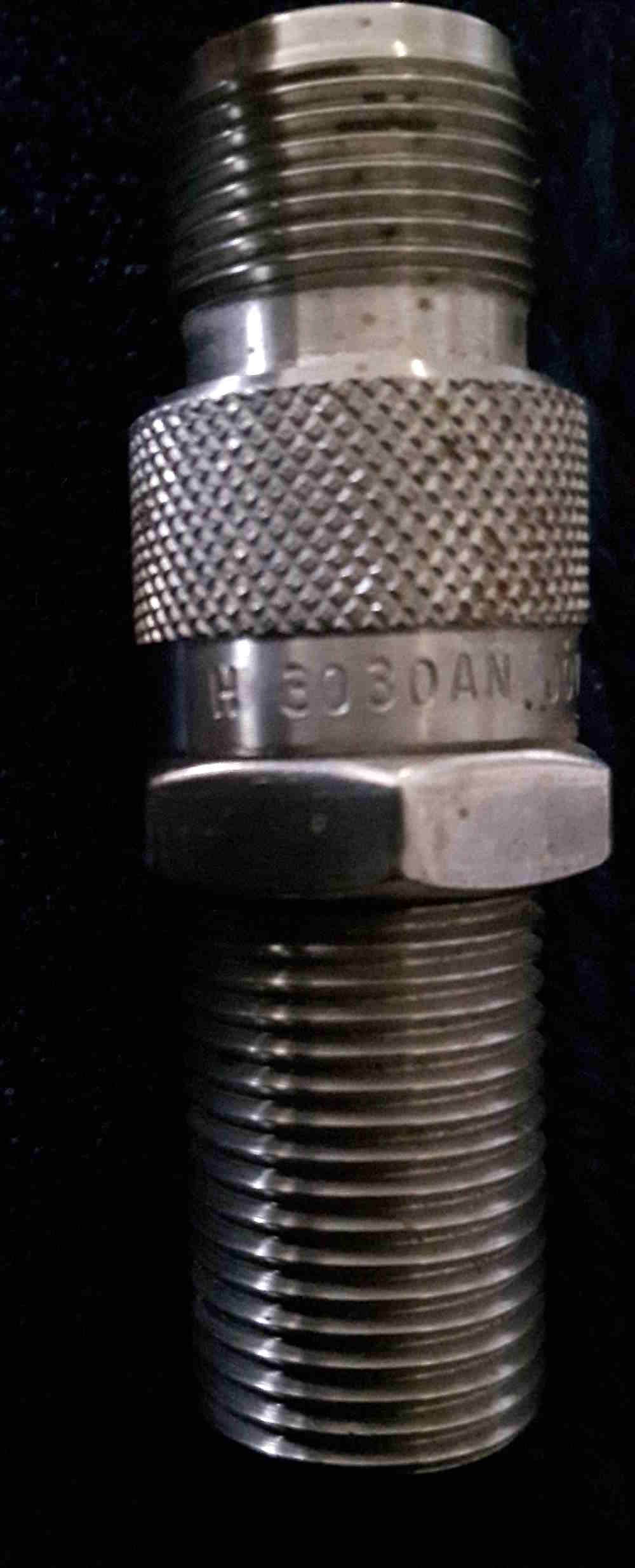
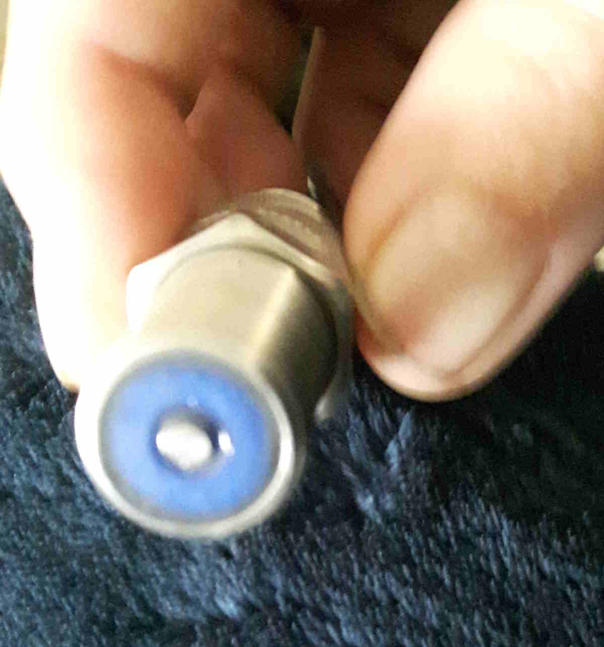
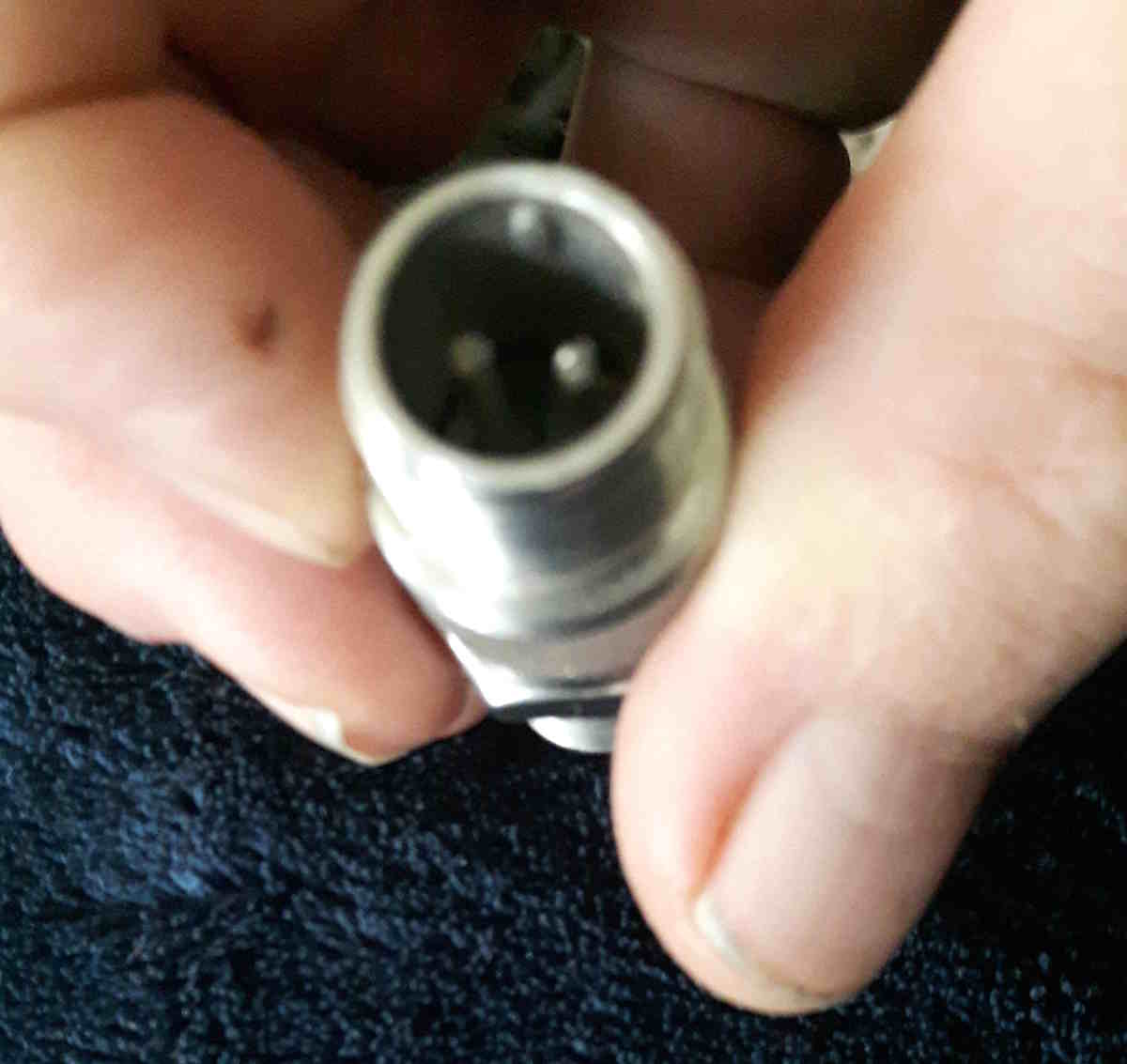
I am attaching photos of a VRS (Variable Reluctace Sensor) by
Honeywell. This sensor was used in liquid flow measurement turbines for
"totalizers". There is two part numbers for different sensitivity. If I
remember correctly this one (H 3030AN) was used on turbines less than
7/8". They have a magnet and core. The core is the small metal piece in
the center of the blue. There is a coil around the core that changes
reluctance when something ferrous comes close to the core. If you
connect a multimeter to the two AN pins and rub the sensor against a
pipe wrench adjuster threads, you can read a frequency or Hz.
Other companies manufacture the same item. Many are used in
industry for speed (RPM) measurement and position sensors. Heavy trucks
have used these for tachometer pickups for years. Very reliable but
heavier and more expensive than automotive hall effect and wheel speed
sensors which I think are VRS.
Dale Davies
The Rotary Engine free News Letter. Powered by Linux. If you
want off
the list PLEASE let me know and I will remove you. ACRE NL web
site.
http://www.rotaryeng.net You Tube
http://tinyurl.com/beqqxas
Copyright 1998-2017 All world wide rights reserved.