12
Is there an after market MAF that would be suitable for our
application and have some of the calibration data with it. I have a
unit that came out of a Ford V8 that dose not have a connector. Are
the connectors available?
Joe Berki
send me a picture of what you have
Paul
On 10/03/2017 08:09 AM, Joseph Berki wrote:
Paul,
Paul, Here are some pics of the Ford MAF sensor. Markings are
F2VF-128579-A2A
AFH70-04
9MO7
Joe Berki
Not that I know of on the after market MAF.
Yes I have a Ford V8 Unit like that.
That mass air flow sensor is about the right size.
Here is a source on connectors and some other info on it.
The software would be easier with an O2 sensor instead of a MAF
sensor.
Paul Lamar
Paul,
Are there any O2 sensors that can stand the lead in Av gas?
Joe Berki
According to Sunoco that is true.
http://www.sunocoracefuels.com/tech-article/race-fuel-101-lead-leaded-racing
-fuels
Are you going to do a lot of cross country?
If you are traveling to an airport where there is no car gas put a
coupling of empty 5 gallon gas cans in the baggage compartment:-)
Take a cab to the local gas station You will probably save a lot of
money.
-----------------------------------------------
Joe, to program with the Mass Air Flow we are going to need to
convert the voltages coming in to an air flow number. As you can see
by this Ford chart it is not a one to one relationship. We need a
look up table.
A look up table is just a bunch of consecutive numbered memory
locations. Like numbered boxes in a post office. What is stored in
the box is the air flow for that voltage number coming in from the
MAF. That part is super simple. Voltage = Pin(x) where x is the
Maximite pin number.
As you can see from this chart the voltages are decimal. So to get
plain simple useful box numbers we can multiply by 10 and chop off
the rest of the decimal number. 0.7 becomes 70 ...
0.75 becomes 74
And so on.
So it looks like we will have 450 boxes. Each box will have an
airflow number stored in it.
Looks like box #70 it will be about 10 Kg per hour or the equivalent
in injector pulse width.
We can adjust these numbers as needed from experience. We can save
these boxes and share them with other people using the same Ford mass
airflow sensor and the Maximite. The whole collection can be
emailed.
That number will be proportional to the injector pulse width.
Is this clear?
Paul Lamar
Paul.
Could we convert the curve too an equation close enough to get the
kg/ hr?
Joe Berki
We could try the square of the voltage times five. The trouble with
that is small tuning changes and specific RPMs and torques are not
possible. However using a leaning knob on the dash may mitigate
that.
Paul Lamar
If you plot the voltage on one axis and the kg/hr on the other Excel
can generate a function that will closely approximate the curve. No
need for a look up table.
Mark LaPierre
Sounds good. To tune it you do another plot?
Paul Lamar
Once you have the formula for the curve you can then calculate the
volume of air from the voltage provided by the MAF. Knowing the
quantity of air you can then calculate the quantity of fuel required.
No real tuning is required. You don't need any feedback from an
oxygen sensor. You can add a variable voltage source controlled from
the instrument panel if you want to add leaning ability.
The formula for the fuel flow would look something like:
#! /usr/bin/perl
use strict; use warnings; my $MAFV; # MAF Voltage my $MAF; # Mass Ir
Flow in KG/HR my $INJECTKGpHR; # Flow rate of injector in KG/HR my
$MFF; # Mass of fuel required in KG/HR my $PWM; # Pulse Width
Percent
# Assume a simple relationship formula for demonstration purposes
$MAF = 7*$MAFV^2
# Assume injector flow rate = 100 KG/HR $INJECTKGpHR=100; for (my
$MAFV = 1; $MAFV <= 15; $MAFV += 1) { # Calulate Mass Air Flow in
KG/HR $MAF=7*$MAFV**2; # Calculate mass of required fuel in KG/HR.
Assume an A/F ration of 17/1 $MFF=$MAF/17; # Calculate Pulse Width
Percent $PWM=($MFF/$INJECTKGpHR)*100; print "Mass Air Flow ".$MAF."
KG/HR: Pulse Width Percent ".$PWM."\n"; }
Mass Air Flow 7 KG/HR: Pulse Width Percent 0.411764705882353 Mass
Air Flow 28 KG/HR: Pulse Width Percent 1.64705882352941 Mass Air Flow
63 KG/HR: Pulse Width Percent 3.70588235294118 Mass Air Flow 112
KG/HR: Pulse Width Percent 6.58823529411765 Mass Air Flow 175 KG/HR:
Pulse Width Percent 10.2941176470588 Mass Air Flow 252 KG/HR: Pulse
Width Percent 14.8235294117647 Mass Air Flow 343 KG/HR: Pulse Width
Percent 20.1764705882353 Mass Air Flow 448 KG/HR: Pulse Width
Percent 26.3529411764706 Mass Air Flow 567 KG/HR: Pulse Width
Percent 33.3529411764706 Mass Air Flow 700 KG/HR: Pulse Width
Percent 41.1764705882353 Mass Air Flow 847 KG/HR: Pulse Width
Percent 49.8235294117647 Mass Air Flow 1008 KG/HR: Pulse Width
Percent 59.2941176470588 Mass Air Flow 1183 KG/HR: Pulse Width
Percent 69.5882352941177 Mass Air Flow 1372 KG/HR: Pulse Width
Percent 80.7058823529412 Mass Air Flow 1575 KG/HR: Pulse Width
Percent 92.6470588235294
You have to use a big enough injector so that the required pulse
width time does not approach the revolution period time else you
will not have any time left for calculating RPM or PWM. This might
not apply if you use the break through bit you sent a note about
where the injectors keep working even if the computer stops for a
bit.
Mark LaPierre
I have my Maximite and MMIDE running!
Scott Gettings
Great Scott.
Fool around with it. Type EDIT and press return. Write a short
program like PRINT "stuff"
and then press F2 to run it.
Paul Lamar
Yes I have done that. It runs basic programs just fine. The MMIDE
editor on the PC mirrors it's input on to the maximite monitor. So I
see the program running on both displays. Also the execution.
I was hoping to be able to use an old iMac 24" computer as the second
monitor, but I can't get this to work due to hardware limitations.
Plain VGA works fine.
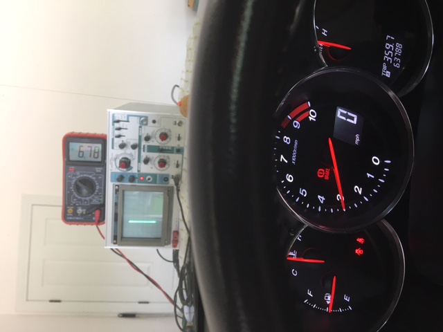
I wanted to determine the normal output of the stock RX8 crank angle
sensor. So I pulled off the bottom engine cover and put a voltmeter and
my oscilloscope tapped into the crank angle sensor leads. It is an AC
output:
3.4 V @ 1000 rpm
6.8 V @ 3000
8.2 V @ 5000
9.2 V @ 7000
These are averages asked on several runs.
Would a Maximite be able to interpret this as part of the fuel injector
calculations? I know we will need two crank angle sensor's for a
simple ignition system, which might be easier to use the adapter plate
and flex plate instead of mounting this hardware on the front of the engine.
Scott Gettings
That can vary too much. A much more accurate way to feed that into
LM1815 and
that will clean it up to one 5 volt plus. This pulse can fire the plugs
and feed
the MM. It can also fire the standalone injector system.
Then use a hard ware Interrupt
"Most external I/O pins can be configured to generate an interrupt using
the SETPIN command with many interrupts (including the tick interrupt)
active at any one time. Interrupts can be set up to occur on a rising or
falling digital input signal and will cause an immediate branch to a
specified line number, label or a user defined subroutine."
That subroutine can read a counter for the RPM(more about that later)
In the back ground between these interrupts
the MM can get the MAF voltage. At 7000 RPM or 117 RPS you then have
time to do
all the other house keeping. .0085 seconds or 8.5 ms to read the MAF
sensor and save it.
And then trigger the injector. If you want to you can skip every other
interrupt to give
you 17 MS for housing keeping. Check the time it takes for the A to D on
the MAF
sensor.
Paul Lamar