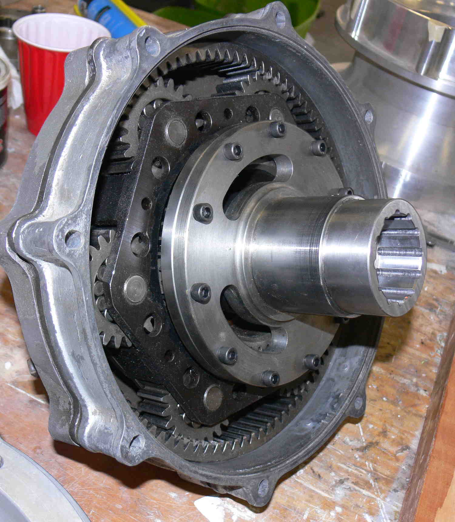
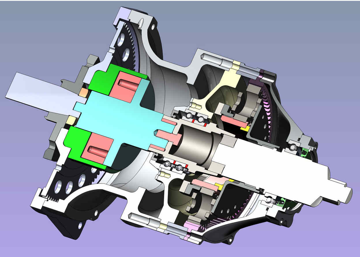
12 f
Paul
I am sending a new design for a damper proposal
with the Ford
transmission drum with a minimum machining, the
aluminum hub part can
be water pressure cutting device for all
straight open holes and the
rest with minimum machining with a small lathe.
I attached some drawings in perspective and
parts list.
JEAN PRUDHOMME
How is this fastened to the Mazda counter weight?
Paul Lamar
The same bolt holes pattern as the original steel part
with conter bore
to hide the head screws
I located
those cap screws locations to screw to the counter
weight, it can be
screw straight to the flywheel and the counter weight
or reuse the
existing steel part as original spacer and flywheel.
Photo showing damper assembly with socket head screw
to attache to the
flywheel and the mazda counter weight
JEAN PRUDHOMME
Jean, I like this proposal, but I am still not clear
on the complete
part arrangement. Can you show or describe all parts
starting from the
aft side housing to the prop reduction drive?
james whitehurst
I think what Jean has in mind is this. Absolutely the
simplest coupling
so far that is likely
to work. Brilliant lite weight design.
Basically you obtain longer socket head metric bolts
that hold the flex
plate on the counter
weight and surround them with small spacer's. This
forms six strong studs.
The actual coupling has larger holes and silicone
rubber is used to fill
the gaps.
It is similar to Andrews CampBell's design. Almost
identical.
Green is steel. Bolts are black and aluminum is blue
in this 3D.
The PSRU input shaft is 1.5 inch in diameter instead
of one inch that
Tracy used.
Extended point set screws can be used to connect the
PSRU input shaft
with the
actual coupling.
There must be a pilot fitting to fit in the end of the
e-shaft to center
the PSRU
input shaft. Not shown yet in this dwg.
Paul Lamar
Paul
It does not need pilot guide the fact as the back of
the drum parts has
a round hub who fit inside on the damper housing
part, the damper
housing housing have the same counterbore who perfect
fit with the Mazda
counter weight, which is different as the aluminum
plate dumper who had
lateral movement
JEAN PRUDHOMME
I don't follow you Jean. Send me a dwg.
Here are your dwgs you sent.
It is too complicate doing it that way.
I am using only six bolts and not twelve.
Far fewer parts. Same basic idea. Toroid rubber
bushings.
Paul Lamar
I did received the aluminum part from the pressure
water cutting , i did
pay extra for a better precision and i find out it
need some machining
to correct it.
If you get it by pressure water cutting make sure your
holes are under
size and you will need to finish on lathe and
pres-drill.
I did order the silicone sleeves medium hard 1.250"dia
and ,625"od steel
tubing for bushing.
As soon i get it i will drill the ford drum plate.
To lower the weight i wont use the flywheel spacer and
bolted the
flywheel straight on the counterweight i know i do
have to make
modification for the stater.
JEAN PRUDHOMME
That looks like it will work. I think it is larger and
heavier than
necessary however. It is about
the same OD we use on the 650 HP time to climb engine.
Of course you might
be planning on that much HP and need it :-)
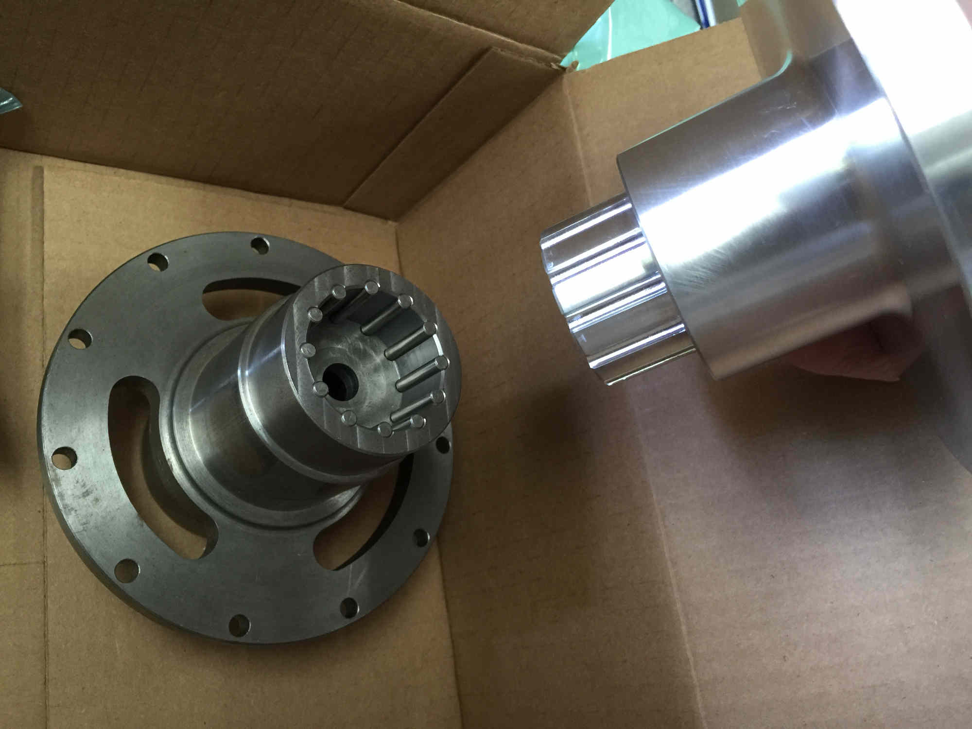
I know you want to use that Ford female spline plate
but you could
machine it down around
the outside of the spline and reduce that diameter.
Image 2234
Then center the big rubber bushing holes on the
mounting screw bolt
circle diameter.
If your worried the spline female part might break
build a static test
rig and check it for
200 foot pounds.
Paul Lamar
Paul
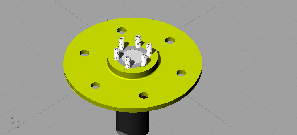
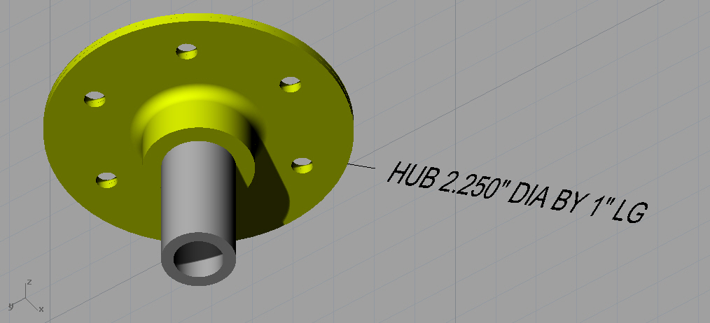
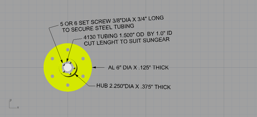
i can use an aluminum front
design with a 4130 1.5" dia tubing as follow but the
each bolt on each side of the al plate i will us steel
washer to prevent wear an enlarge surface for
strength.
JEAN
PRUDHOMME