12 k
Does anyone have a rd1c installation guide or advice. I want to check
before bolting the psru back up for engine runs. Wasn't there a viton
seal recommended to seal the bearing/thrust washer stack against the
motor mount plate? Alex Molteno Yes but I recommend Teflon. Paul
Lamar
I will see if I can dig up my RD 1C manual and email it to you
directly. Scott Gettings.
Alex, The teflon disc goes between the input gear and the inner
surface of the planetry reduction to stop metal to metal when you
pull power and the input shaft can be drug forwards. The prop shaft
goes through the center of the teflon disc. Bearings go against the
plate, and make sure you have a low pressure seal in the plate. A
low pressure seal has one lip only, a high pressure, two or double
lip. Little pressure in the housing so the low pressure seal does a
much better job of sealing as is more flexible.
Neil Unger.
Ok thanks Neil,
Alex Molteno
Hi Neil, do you have an illustration or picture to show the location
of the discs on your drive. My engine has run time on a stand for
about an hour when it belonged to Milo Burroughs and there is a
slight bit of wear on Tracys motor mount plate at the rear of the
drive. I initially figured thats what you were talking about when
you said it needs the teflon disc, to stop any metal on metal
rubbing when the shaft is not being pulled forward, for instance when
the prop is driving the engine on steep descent,
but as i understand it, you recommend to put another disc at the
opposite end too for when power is applied and the shaft is pulled
forward to metal on metal contact
So 2 discs needed then. Do you remember what thickness you are using
for the forward disc, so it doesn't tear it up?
Alex Molteno
That is kind of surprising as those are thrust roller bearings. They
should not need teflon.
Paul Lamar Alex, There is one nylon or teflon disc only, not two.
The Nylon disc which tracy called the "snubber" bearing goes between
the front face of the gear on the input shaft and the inner face of
the planetry. The prop shaft comes through the front of the
planetry (splined) and then through the "snubber" disc with the
polished end of the prop shaft then finishing up inside the center of
the input shaft which has a brass bush pressed into it. THis makes
both the prop shaft and the input shaft almost rigid. The bearing
stack which consists of, 2 thick thrust washers which are each end of
the bearing stack, a pin roller thrust bearing (2 of) fits inwards of
each thick washer,(one each end) with a thin thrust washer going in
the middle of the 2 pin roller bearings. (middle of stack) The
bearing stack has a thick thrust washer-- a pin roller bearing -- the
thin center thrust washer -- another pin roller bearing and then
another thick thrust washer.
The bearing stack slides onto the back of the input shaft. The
bearing stack sits directly onto the Tracy plate and the rear thick
washer should not turn at all. Each thick thrust washer at each end
of the bearing stack should not turn. The rear washer is stationery
on the mounting plate and the front washer turns with the input
shaft. The turning is done by the 2 pin rollers and thin intermediate
thrust washer only. You say there is wear on the mounting plate---
Make sure that the rear most thick washer is not binding on the input
shaft. It must be free to turn without binding on the input shaft
under any circumstances.
Clearance is checked by standing the PSRU on the prop shaft
vertically, removed from the mounting plate. It may be best to
remove the thick rubber O ring that holds the ring gear of the
planetry in place while you do this as the 2 halves of the PSRU must
be in full contact with each other to not give a wrong clearance
reading. 2 clamps will do the same thing just so long as there is nil
gap between the 2 halves.
Remove the input shaft and bearing stack. Drop the nylon snubber
washer over the prop shaft that protrudes from the planetry assembly.
Then drop the input shaft down so that the protruding prop shaft is
inserted inside the gear (brass bush inside) and resting firmly on
the nylon "snubber" washer. (this is the one and only nylon
washer). Place the bearing stack over the end of the input shaft and
they should just clear a straight edge put across the PSRU housing
that is to bolt onto the mounting plate.
I work on a min of 5 thou, but is not that critical, just so long as
there is clearance. If the bearing stack is proud of the housing, the
nylon washer is to be thinned down, or replaced with a thinner one
until the bearing stack is clear of the afore mentioned straight
edge. (I use a steel ruler as it is not all that critical, just has
to clear)
Under load the input shaft rests on the bearing stack due to the
helical cut of the gears, (rearward force). Pull the power so that
the prop now drives the PSRU and the gears (helical) will pull the
input shaft forwards. The nylon snubber washer takes up any forward
thrust pressure preventing metal to metal contact. Probably clear as
mud?? Ask me for clarification where necessary. Neil Unger
Hi Neil, How exactly are you stopping the outer planet ring from
turning. Also what do you think the torque load is that makes the
ring gear want to rotate, is it big or reasonably small. Cheers Chris
Hoskins in NZ
Chris,
I am talking Tracy Crook's PSRU. It is
mounted on the sprag gear that comes with the planetry combination.
Tracy holds the sprag gear in place with 6 x 1/4 inch screws. These are
prone to come loose and shear off.
In my PSRU the ring gear is held in the rear section of the alloy
housing with a close tolerance fit. loctited, and held with extended
point screws that are drilled into the ring gear. The torque turning
load I feel is reasonable great as it has to stop the Planetry from
turning the ring gear. We have 250 HP attempting to turn everything or
a torque of 300 FT pounds if I remember correctly. This will lessen as
the diameter increases. My extended point screws are at the outer of
the ring gear which gives the maximum leverage available. So far so
good at approaching 50 hours.
Neil Unger the OZ peasant.
Yeah sure :-)
Paul Lamar
Thanks Neil,
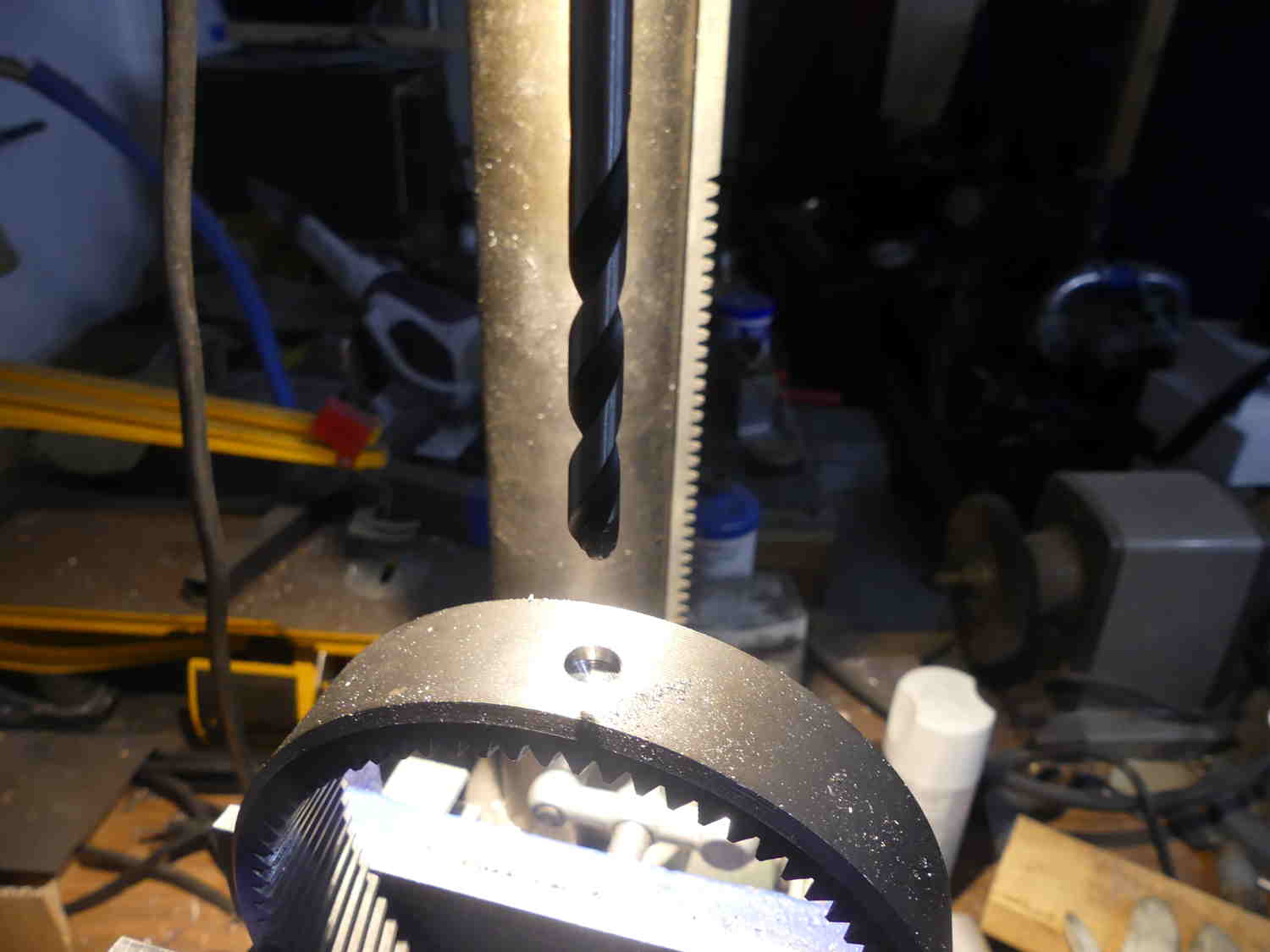
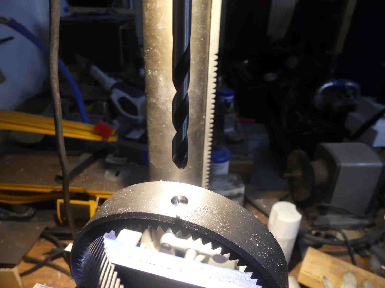
How did you drill the holes ? I tried with a carbide tipped drill
and it wouldn't even look at it, maybe I needed to use more force huh.
How would get the ring gear out if necessary ?
Cheers Chris Hoskins NZ
It does take a lot of pressure.
Here is a picture I just did. 1/4 inch hole.
BTW on the sun gear you do not need extended point set screws. Just
use short rods and just tig weld them in. Saves taping hard steel.
Paul Lamar
------------------------------------------------------------------n
Please add your questions or comments at the end of the thread.
Not the beginning.
I am going to enforce that rule. If people don't do that it will not
be forwarded. My ISP changed the rules.
The Rotary Engine free News Letter. Powered by Linux. If you want off
the list PLEASE let me know and I will remove you. ACRE NL web
site.
http://www.rotaryeng.net You Tube
http://tinyurl.com/beqqxas
Copyright 1998-2017 All world wide rights reserved.