12
2018.03.30
Hi Paul,
another impressive video, making the combustion process visible ;-)
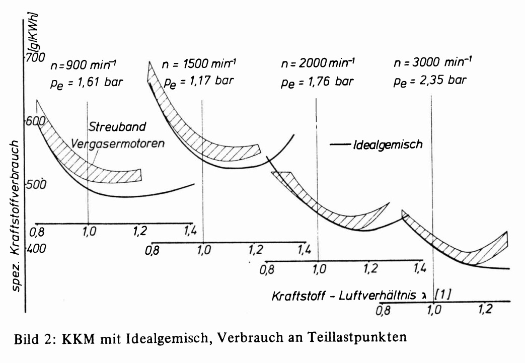
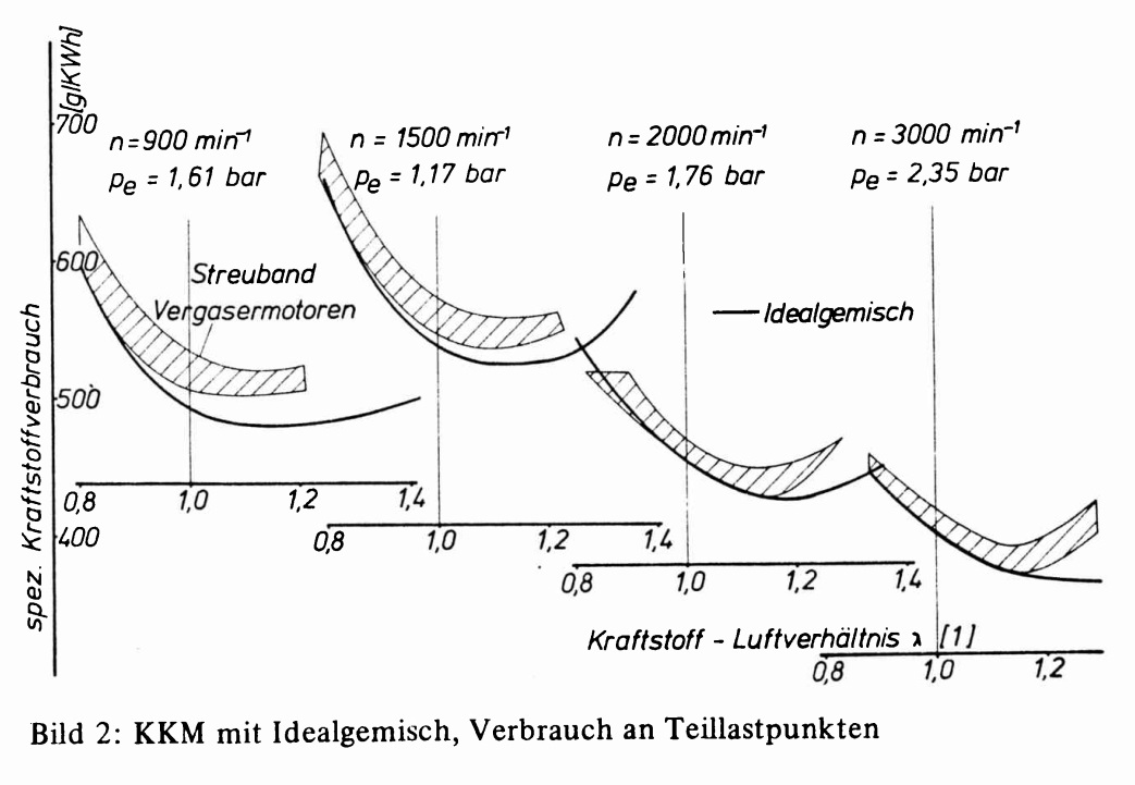
With regards to processing a homogeneous mixture, I've found a german paper,
dated 1976.
Engine was a NSU KKM 871, 2 rotors.
For preparing an ideal mixture they've used a "boiler" / drum. Fuel was
heated up to 200°C + fed into the boiler / big chamber. Mixture temperature
was 70°C out of the boiler with all fuel evenly vaporized. Intake
temperature at ports was ~ 65°C.
Compared to a conventional downdraft carburetor you can see some advantages.
» pict_1
spez. Kraftstoffverbrauch » specific fuel consumption in g/kWh
KKM » RE
Idealgemisch » ideal mixture
Vergasermotoren » engines with carb
Kraftstoff-Luftverhaeltnis » Relationship of fuel + air » Lambda
Teillastpunkte » part load "points" / adjustments
Without the availability of fuel injection David Garside has found a very
good solution for the Norton motorbike: air gets into the carbs with ~
100°C + will be cooled down because of fuel evaporation to ~ 50°C before
reaching the chambers. He has used SU carburetors (variable venturi /
constant velocity carbs) - they ensure a pretty good fuel spray.
In general there are some rules of thumb, one may pay attention to ...
» duration of evaporation of a gasoline droplet » at 30°C it takes 8 times
longer than at 80°C » higher temperature is preferable
» 8 million droplets with a diameter of 10 µm will evaporate 200 times
faster than 1 droplet with a diameter of 2 mm (same volume) » the smaller
the droplets the better
With fuel injection into the intake manifold or PFI ...
» higher flow velocity in the intake manifold enhances fuel preparation
» lower pressure in the intake pipe (e.g. at WOT) enhances evaporation, too
It's preferable to get fuel droplets as small as possible. That's why the
Renesis engine has primary injectors / nozzles with 12 holes, generating a
relatively fine mist of fuel.
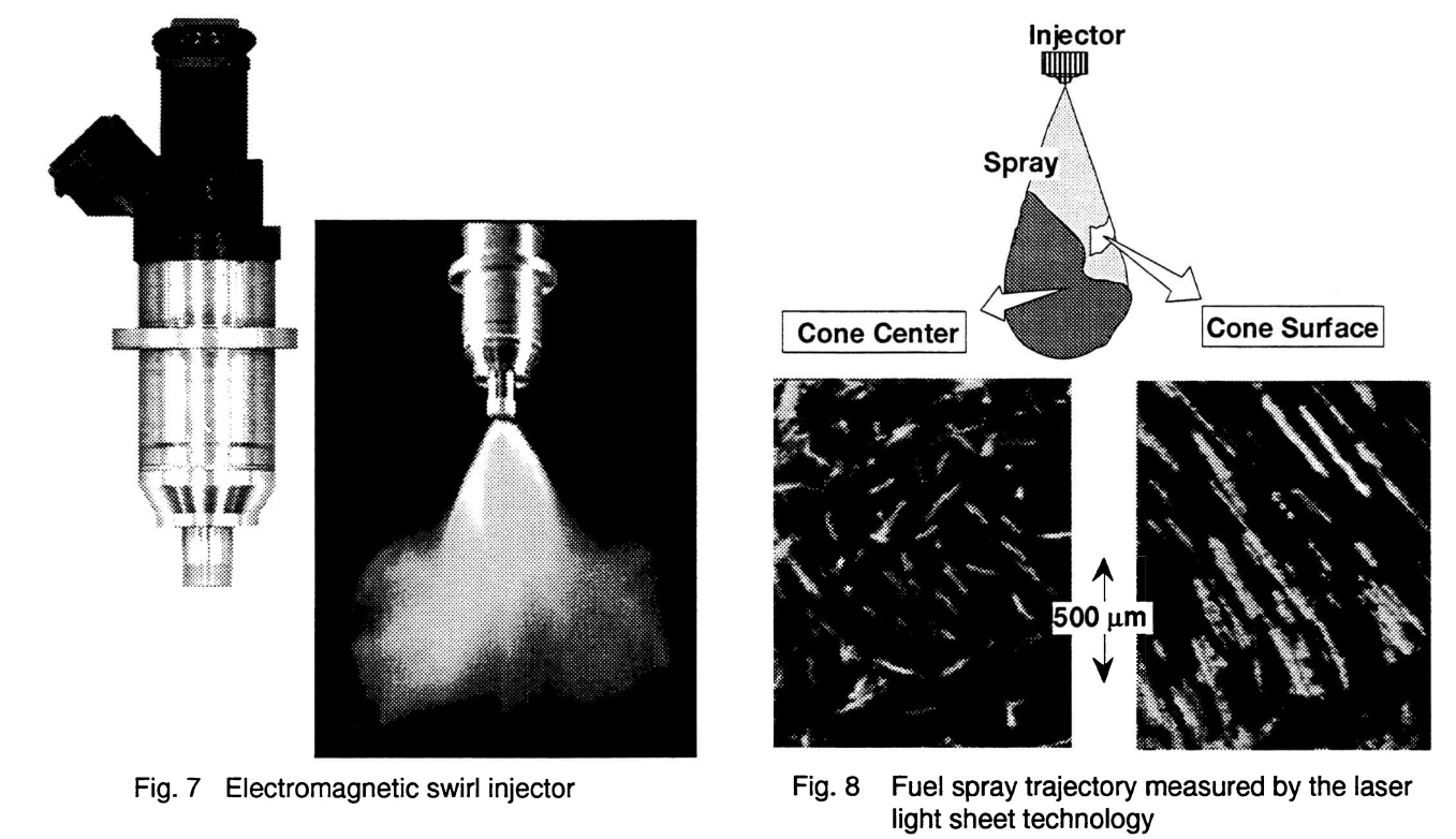
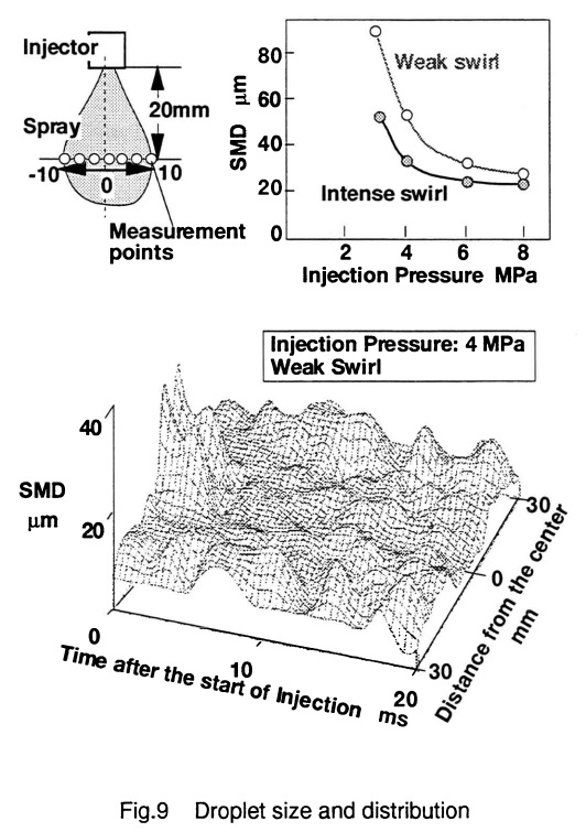
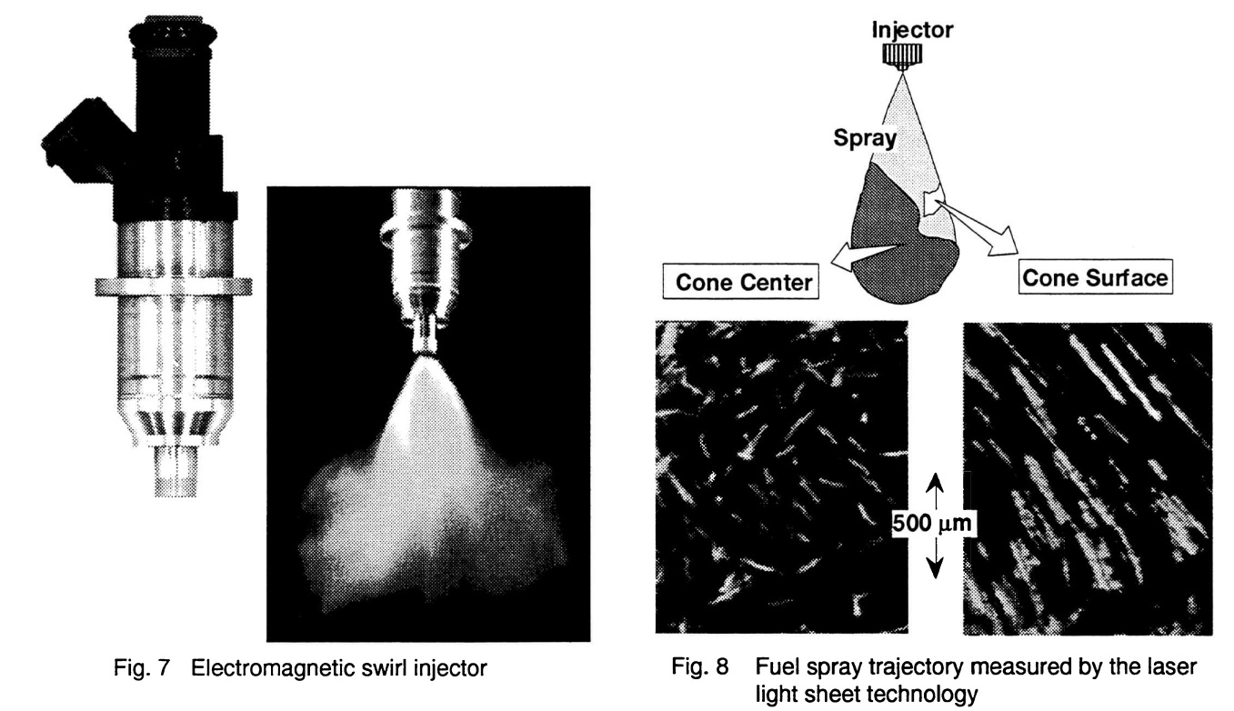
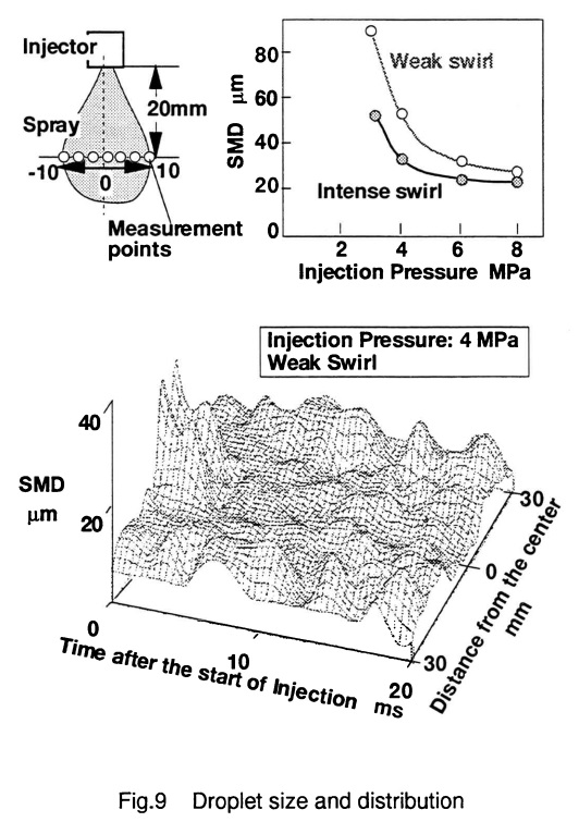
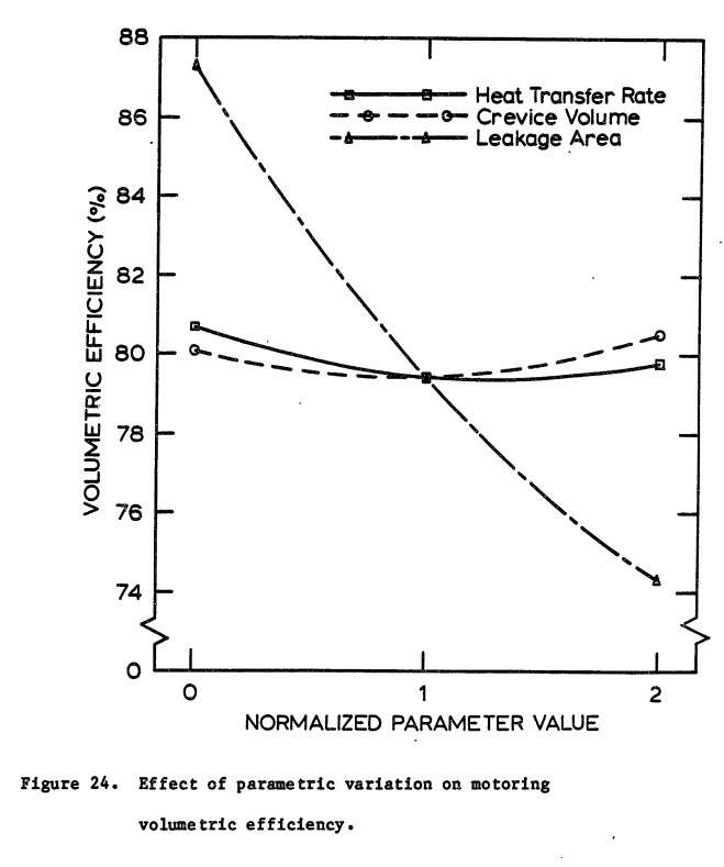
Another solution may be a swirl injector like the one by Mitsubishi, 1996.
» pict_2 + pict_3
Very small SMD (Sauter Mean Diameter)
Once the mixture is inside the engine, it's important to avoid condensation
/ fall-out of the gas. Was a very big challenge for Daimler-Benz with the
DFI system. Therefore the walls should have a temperature of at least ~
40°C. More is better. That's one of the reasons to "heat" the cold lobe a
bit ;-)
(Another one is to avoid deformation of the housing shape)
The disadvantage with warm / hot mixture + walls is, that volumetric
efficiency will decrease. Again, finding the right balance is the target.
Quenching ...
sorry, the next part is a bit "academic" ;-)
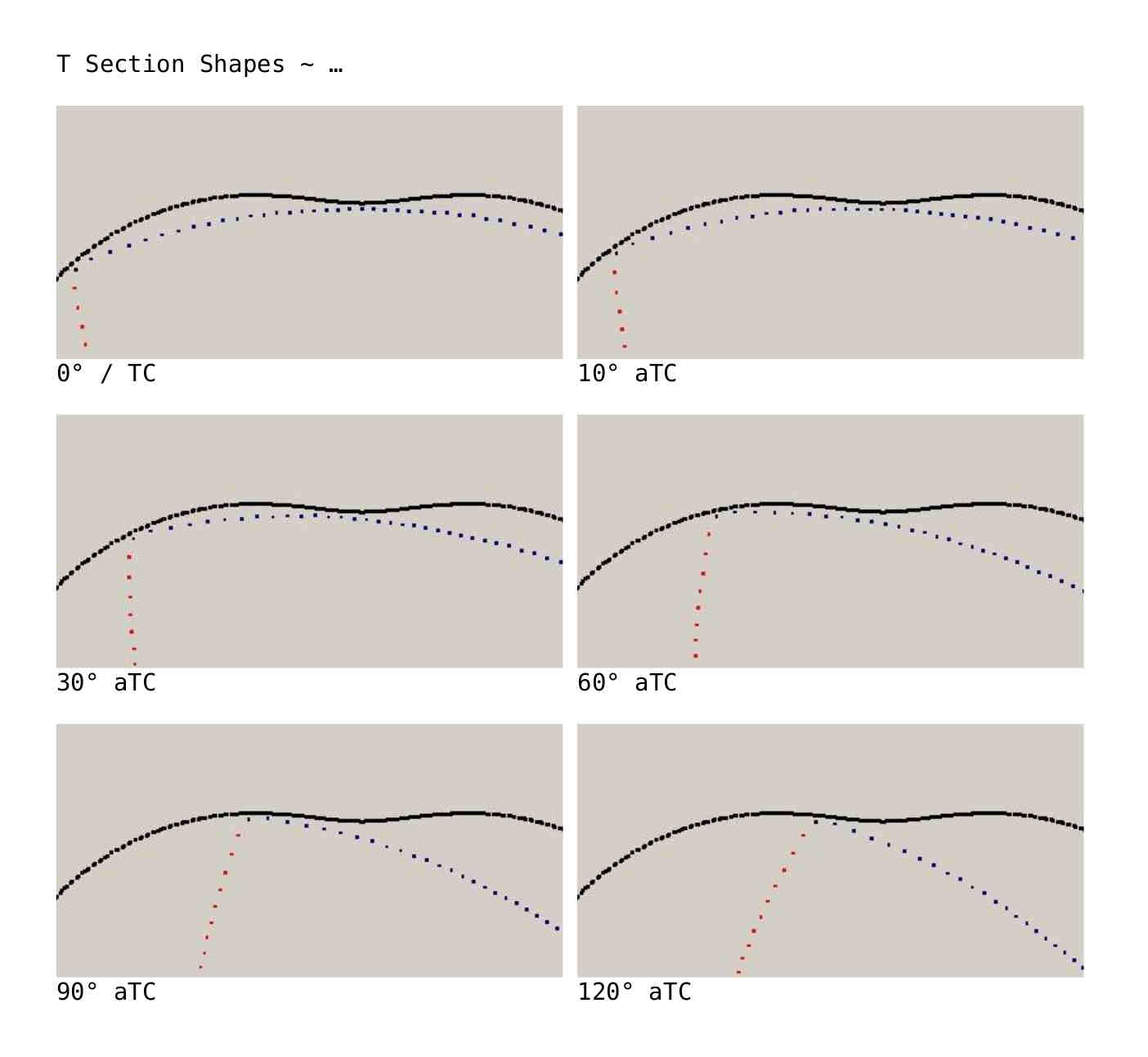
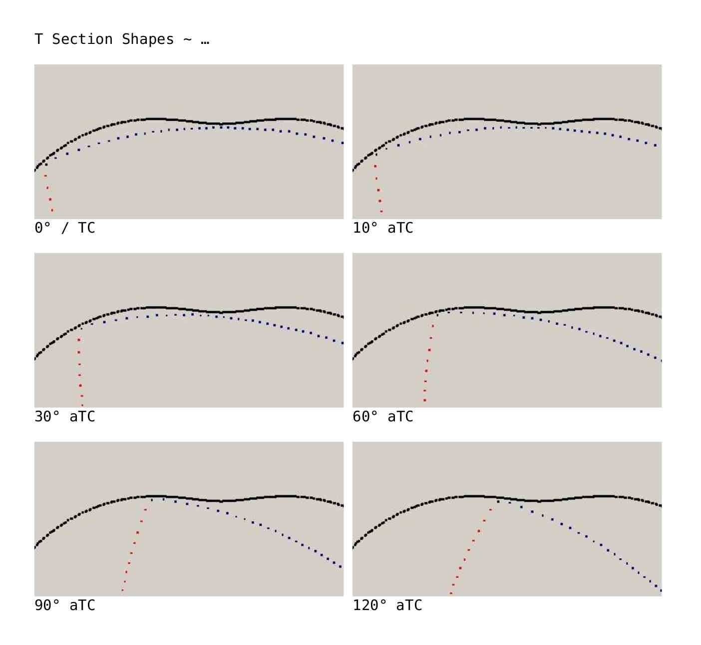
Related sketches: t-section.pdf
At all walls of a combustion chamber you will have a wall layer - a thin
film of gas, that will not be burned.
Reason: heat loss to the walls is greater than the amount of energy produced
by combustion » extinction of the flame front.
Wall layer will be smaller / thinner with ...
» higher pressure (exponential effect - good)
» richer mixture (simply more energy available)
» higher wall temperatures (limited by compulsions of lubrication)
The thinner the "chamber" the richer the mixture has to be. But this will -
of course - increase heat losses ...
Near the "cool" walls the disintegration of molecules + atoms of fuel will
be stopped. Termination of chain reactions, free radicals will partly be
bound to the wall + converted into stable species.
Sorry, have forgotten the minimum temperature levels you need for
satisfactory chemical division.
No further chemical reaction will occur - that's the main issue /
challenge. There will be no more conversion, e.g. CO to CO2. That's the
phase, where you will loose a lot of energy / heat / power ...
A simple combustion model may make it more clearly (?) ...
1st step: emergence of short chains (Alcanes ?)
2nd step: appearing of radicals like H, O, OH ... (Alcenes ?)
3rd step: "cold flame", generating ~ 10% of the energy / heat
4th step: "blue flame", you will "see" CO, H, H2O. Oxidation to CO delivers
~ 30% of the heat. This phase may be (partly) not reached in the quenching
areas.
5th step: the main heat / energy producing step. Most of the time this will
not be reached in the spheres / sectors of quenching: conversion of CO to
CO2. This step generates ~ 60% of the heat / usable energy. + only just now
you can measure the big / huge rise in temperature.
Sorry, my English isn't good enough to explain everything correct. We would
need a chemist now ;-)
Another challenge will be to initiate combustion In the mixture + not at the
edge. Flame front is "creeping" along the sliding surface + will be cooled
down unnecessarily. Possible countermeasures ? Perhaps laser or some kind of
"jet" ignition ... ?
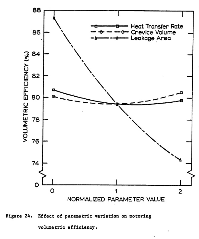
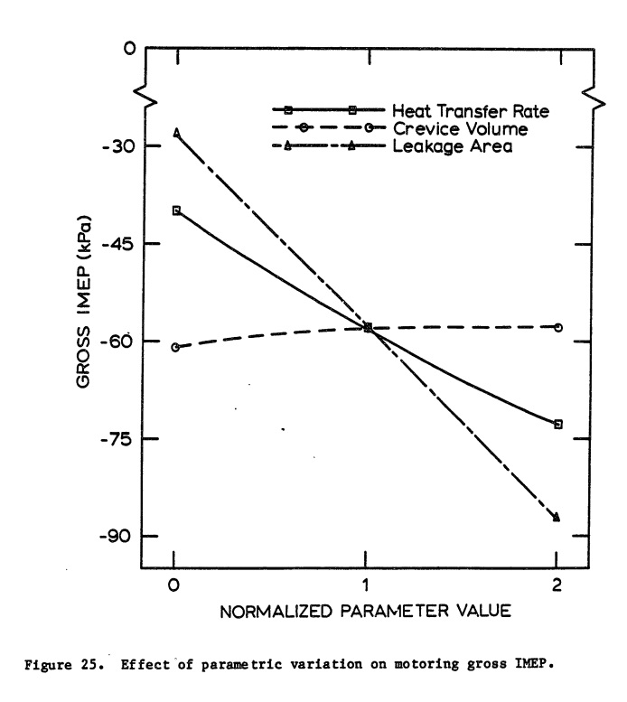
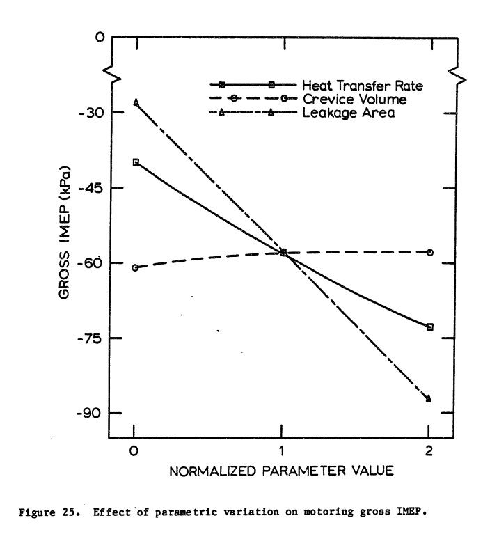
After all, picture_4 + picture_5 show the influence of heat loss, crevice volume +
leakage. The last point is the most important ...
But now it's really time to "shut my mouth". So much blah-blah ... ;-)
Best regards
Franky
------------------------------------------------------------------
Please add your questions or comments at the end of the thread. Not
the beginning.
I am going to enforce that rule. If people don't do that it will not be
forwarded. My ISP changed the rules.
The Rotary Engine free News Letter. Powered by Linux. If you want off
the list PLEASE let me know and I will remove you.
ACRE NL web site.
http://www.rotaryeng.net
You Tube
http://tinyurl.com/beqqxas or PaulLamar2
Copyright 1998-2018 All world wide rights reserved.